Summary of How to Build an Arduino Powered Chess Playing Robot using arduino
This project describes an Arduino Mega–based chess-playing robot that uses a movable magnet on an XY gantry to pick up magnetized pieces and 64 reed switches under the board to detect piece locations. The author details parts, mechanical assembly (drawer bearings, stepper motors, rack gears), wiring, and a coordinate-mapping scheme converting base-10 square IDs to base-8 (x,y). The build worked but had issues with an overly strong magnet pulling extra pieces.
Parts used in the Arduino Powered Chess Playing Robot:
- 1 Arduino Mega
- 1 Mux Shield
- Motor Shield
- Large chess board with pieces
- 64 NO Reed Switches
- 16 10K 1/4 Watt Resistors
- Roughly 90 feet of 30AWG Wire
- Neodymium Magnets to fit your pieces (disc magnets)
- 1 Large Neodymium Magnet (used as actuator)
- 2 Pairs of 24 inch Drawer Bearings
- 2 Stepper Motors
- 2 Vex Rack and Gear Sets
- 1 Standard Hobby Servo
- 1 2 ft x 2 ft Perf Board
- 1 2 ft x 2 ft x 1/2 inch MDF Board
- Various lengths of scrap 1x2 wood
- 5 Minute Epoxy
- 1 Wood Saw
Judging by the sheer number of chess related Instructables, I think it’s safe to say the community enjoys the game. It can be difficult, however, to find someone who plays on the same level you do. To solve this dilemma, and to increase my playing skills, I built this arduino powered chess playing robot.
The board works like any other xy table, with a few key differences. First, the x axis has an extra servo attached to it, which raises and lowers a magnet. The magnet is attracted to pieces on the chess board above, allowing them to move. Second, embedded in the board are 64 magnetically activated reed switches, allowing the arduino to know the location of each piece.
What I love about this project is its adaptability. If you decide you’re done with it as a chess board, it can instantly convert into a CNC mill by modifying a few pieces. I’ll talk more about this possibility at the end.
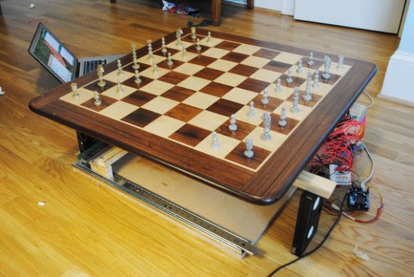
All in all, though I learned a lot from this project and had fun building it, the board was not as successful as I had hoped. The magnets were way too powerful, so extra pieces would almost always drawn in when they shouldn’t have. However, with a few thoughtful changes I think this could have been a better, more functional project. Until I build another, better board, though, I think this Instructable still serves as a pretty good guide to make your own chess robot.
Step 1: Parts and Materials
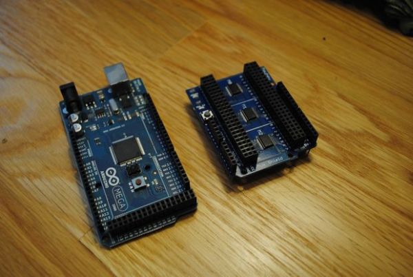
- 1 Arduino Mega
This is the most expensive item in the project. It’ll be dealing with the inputs from each chess square to let the computer know where you’ve moved. We’re using the mega here due to its speed and number of inputs. Adafruit $65
- 1 Mux Shield
The mux shield (short for multiplexer) gives us even more inputs for our arduino mega. We’ll need 64 inputs in total, one for each square. Sparkfun $25
- Motor Shield
The motor shield will be controlling our stepper motors and servo. You’ll need to solder it together. Adafruit $19.50
- 1 Large chess board with pieces
This one is a little more self explanatory. We want a large chess board here because the pieces need to be able to move in between each other with disrupting others. Make sure you measure the diameter of the bottoms of the pieces. We’ll need that in a moment. I’m not sure where mine is from, but you can pick them up from a flea market for a bargain. The playable area of my board is 24″.
- 64 NO Reed Switches
Reed switches are magnetically activated switches. They’ll help us find the location of moved pieces. NO stands for normally open, that is, the circuit is disconnected Digikey ≈$30
- 16 10K 1/4 Watt Resistors
These are the pull up resistors for the built in digital pins. The mux shield, luckily, has integrated pull downs, so we don’t need to worry about those. Digikey ≈ $2
- Roughly 90 feet of 30AWG Wire
This is the hookup wire for all of our sensors. Radioshack ≈ $16
- Neodymium Magnets to fit your pieces
This is where the measurements from the bottoms of your chess pieces come in handy. You’ll need disc magnets to fit underneath each piece. For proper strength, they should be about 1/8″ think. A great source for these is K&J Magnetics. ≈ $55
- 1 Large Neodymium Magnet
Note: This was Waaaay too powerful. It would draw in pieces it shouldn’t have. You’d be better off going with some smaller ceramic magnets, like you’d find at Staples or another office supply store.
- 2 Pairs of 24″ Drawer Bearings
The size of your bearings will depend on the playable area of your chess board. These allow for the stepper motors to move back and forth underneath the board. Amazon ≈ $30
- 2 Stepper Motors
Stepper motors can move in very precise increments. In the late 90s they were in just about every piece of tech you could find. The best place to get these are in old dot-matrix printers. You can them at the flea market for next to nothing!
- 2 Vex Rack and Gear Sets
The rack gears allow the stepper motors to travel on the drawer bearings. See the Step 4 for a more detailed explanation. Vex Store $40
- 1 Standard Hobby Servo
This servo will be raising and lowering the powerful magnet below the board. You can find them at a hobby shop for ≈ $10, or Amazon ≈ $12
- 1 2′ x 2′ Perf Board
The perf board is super thin and will be the mounting surface for all of our reed switches. The price will vary greatly on this one, but I got mine from Home Depot for ≈ $5
- 1 2′ x 2′ x 1/2″ MDF Board
Similar to the perf board, I got this from Home Depot for ≈ $5
- Various lengths of scrap 1″x2″ wood
This wood forms the bridge between the X-Axis drawer bearings. Go behind any hardware store and you’ll see dumpsters full of this stuff for totally free!
- 5 Minute Epoxy
This stuff is a godsend. It’s used for just about everything in this project, from mounting motors to attaching the rack gears. I’m in love — and I picked mine up from Radio Shack for $3
- 1 Wood Saw
You probably already have this one, but if you don’t, I picked mine up at Ace Hardware for $10 a couple of years ago.
Step 2: Design and Code Explanation
That parts list is a bit scary if you’re not sure what everything is going to do, so here’s how many of the pieces will be used.
You can see in the images below that each stepper motor can move freely about its axis thanks to the drawer bearings. On the Y Axis, each rail is connected with the wooden structure, so that the X Axis may sit atop it. Also on the X Axis is the servo that raises and lowers the powerful magnet, so that it may position itself before moving pieces.
Feel free to download the sketchup file and mess around if you’re not sure of anything.
Another interesting element of this design is how to code talks with the arduino and motors. We need to address each square as a set of coordinates so that we may find slope and distance, however the traditional method of labeling squares A1, A2, etc. doesn’t work particularly well in code. Standard (x,y) coordinates are much friendlier. Those coordinates, however, need to be in the form of a single number. What I ended up doing is assigning each square to a number, as you can see in image #3. Those numbers don’t really work as coordinates on an 8×8 chess board, however, because we use a base 10 number system.
To solve that issue, we take the base 10 number of each square and convert it to base 8 using the modulus operator in C. 27, for example, is 33 in base 8, with the first digit being the x coordinate and the second the y. If you count over three squares and up three squares, voila! You end up on square 27. This converted coordinate system ends up looking like image #4.
Step 3: Mounting the Drawer Bearings (Y Axis)
The drawer bearings are what allow the axes to move in their respective direction. The mounting instructions may vary slightly depending on the brand, but usually it’s as simple as driving a couple of screws.
The only reason I’ve made this its own step is that aligning the bearings perfectly is key. Should you fail to do this, and they both point slightly outwards, they’ll stop at some arbitrary point and refuse to move once you connect them. Save yourself a lot of trouble and use something you know is square as a reference for alignment. The corner of a book is perfect.
Step 4: Building the Motor Mount (Y Axis)
The stepper motors we’ll be using have fantastic torque, but are circular. This means mounting them to our bearings later on will be nearly impossible, unless we build a square mount. To build one, find a hole saw with a similar diameter to your motor. You’ll want to use a drill press rather than a portable drill for this, so I borrowed my school’s.
Once you’ve cut the hole, slice the circle in half to get two mounts. This chipped the tips of my semicircle, so I used some 220 grit sandpaper to clean up the edge.
My steppers came with mounting screw holes, which line up well with the wooden frame. I used the smallest screws I could find. Mine fit so well that it wasn’t necessary, but you might consider adding a bit of epoxy to strengthen the bond.
Step 5: Installing the Rack Gears (Y Axis)
The rack gears are what allow the motor to latch onto a surface to pull itself along. Your physics teacher probably defined them as a way to convert rotational energy to linear.
Again, we use the epoxy to attach the gears onto the MDF. In addition to heavily applying epoxy to the board itself, make sure some is spread on the side of the drawer bearing, that way there is stability in two dimensions. Do your best to prevent epoxy from getting in places it shouldn’t be — you may gum up your motor.
It works out that the rack gears extend a little bit off of each end. This is a good thing — it enables the gear to travel the full length of the board without running off. The stepper motor will be offset just enough that if the gears only covered the board’s length the whole motor assembly would get stuck at one end.
Also install the circular gears onto your motor at this time. Mine had a set-screw, but you may wish to use some JB weld to hold your gear in place. If you go that route, the joint needs to fully cure before you try to use it, or you risk the gear popping off!
Step 6: Wiring and Mounting the Motor (Y Axis)
The leads that come attached to the stepper motors are very short. Because the Arduino is mounted off the board, the wires need to be at least the length of one side. That made mine about 2′ 5″ long. Heat shrink tubing is your friend here — we’re using enough power that it might arc if you’re not careful.
If your stepper motor has 5 wires, you’re all set. If there are 6, however, it means you have to connect your center taps. Jason Babcock has a great tutorial on reverse-engineering your motors. In my case, however, the wires were the same color.
After extending the wires, the center taps go into the center of one of your motor hubs. The wires from one coil go to one terminal on the motor shield, and from the other coil to the other terminal. At this time we also hook up our 24v 1A power supply to the motor shield. If you get the polarity wrong on this, your motor shield is toast.
After trimming the motor mounting block to about 4 inches, it’s time to attach it to our bearings. Mix up the epoxy, and liberally apply it to the area of the bearing the block will touch.
Also, if you have any pets, be sure to animal-proof the room you’re working in. Cats seem to have an affinity for knocking over things that are drying.
For more detail: How to Build an Arduino Powered Chess Playing Robot
- What microcontroller is used in the project?
The project uses an Arduino Mega as the main microcontroller. - How does the robot detect piece locations?
It uses 64 normally open reed switches embedded under the board to detect magnetically activated pieces. - How are pieces moved on the board?
A movable magnet mounted on an X axis and actuated by a servo raises and lowers to pick up magnetized pieces while stepper motors move the gantry. - Why is a Mux Shield required?
The Mux Shield provides additional inputs so the Arduino Mega can read all 64 reed switch inputs. - How are the X and Y axes implemented mechanically?
Drawer bearings serve as rails, stepper motors drive Vex rack and gear sets, and a wooden frame supports the axes. - What issue did the builder encounter with magnets?
The large neodymium actuator magnet was too powerful and drew in extra pieces unintentionally. - How are board squares addressed in code?
Each square is assigned a base 10 number which is converted to base 8 using the modulus operator to produce x,y coordinates. - What power supply is used for the motors?
A 24V 1A power supply is connected to the motor shield for the stepper motors. - How are stepper motors mounted to the rails?
Circular motor bodies are mounted in semicircular wooden mounts made from a hole saw cut and attached to the drawer bearings and frame. - Can the device be repurposed for other CNC work?
The author notes it can be converted into a CNC mill by modifying some parts.