Summary of Build A Simple Robotics Breadboard Using Arduino
This article details the construction of a low-cost, solderless robotics breadboard named "Babuino" for non-programmers. It outlines assembling a mechanical chassis using a standard breadboard, Pololu motors, and DIY wheels from plumbing plugs. The guide covers mounting batteries, a roller ball, and essential electronic components like LEDs, buttons, capacitors, and an L293D H-Bridge motor controller. Two versions of the Babuino controller are described: one using a standard Arduino clone and another with built-in USB capabilities, enabling easy experimentation without complex tools or permanent soldering.
Parts used in the Babuino Robotics Breadboard:
- Solderless Breadboard
- Pololu Motors
- Pololu Roller Ball
- Battery box for 4 AA Batteries
- Battery box for 2 AA Batteries
- Foam Tape
- Pipe Plugs
- Large rubber bands
- LEDs
- Resistors (220 Ohms to 1K Ohms)
- Push Buttons
- Capacitors (Electrolytic and Ceramic)
- Buzzer
- Ceramic Resonator
- Voltage Regulator IC
- L293D Dual H-Bridge IC
- Microprocessor (Arduino/Freeduino)
- #2x1/4 inch wood screws
- Scrap plastic disks
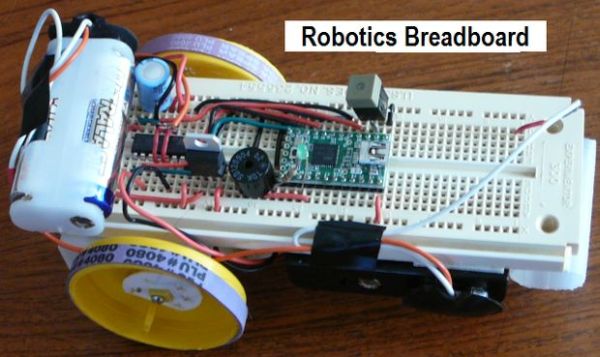
This Instructable shows you how to build a simple, inexpensive breadboard for robotics experiments. It is a companion to Cheap, Easy Robotics for the Non-Programmer. Here we’ll learn how to build a Babuino robot to use for experiments with the Babuino/Blocos software environment. Using a breadboard like this makes it easy to experiment with robotic circuits. Since no soldering is required, it’s also very easy to make changes to your circuits. (Note that some soldering is required to build the breadboard, but it’s pretty minimal.)
This website (featured in the last Instructable) provides a great design for a simple robot. That platform is both simple and elegant, but has two short-comings for an individual wishing to experiment with robotics. The first is that the platform really wants to be built for a class. That is, the tools and setup to build it may be beyond an individual who does not have a fairly complete shop (like a band saw or jig saw) and the materials become economical when purchased in quantity. The other short-coming is that the platform is fairly specific once the Radio Shack prototype board is built. Sensors, motors, etc. are soldered in place, so making changes is difficult.
There are many other examples of simple robots and Arduino clones on the Internet. Pointers to some of these were given in the last Instructable, and lots more can be found with Google. So why am I reinventing the wheel? Simply to bring together in one place all the pieces you need to build a robot breadboard, complete with motors and motor controls, at minimal cost and assembly effort. Add the environment from the last Instructable and have a blast with robotics for a tiny investment.
First, I’ll show you how to build the mechanical platform, then we’ll add the Babuino controller. Two alternative Babuino incarnations will be presented. The first will be an actual Arduino clone, using the same processor used on Arduino and having exactly the same hardware resources. The second is a simpler to use version with a built-in USB interface and additional hardware resources. Both will work great, pick your favorite.
Important Note: When I use the name “Arduino” I mean not just the (not quite copyrighted) Arduino itself, but also the many public domain versions collectively known as “Freeduino”. In some cases I use the term “Ard/Free-duino”, but the terms should be considered interchangeable for the purposes of this Instructable.
Step 1: Assembling the Robotics Breadboard – Part 1: Mechanical
Here are the mechanical parts need to build the robotics breadboard. Suitable suppliers are listed for most of these although there are many alternatives you can use.
Mechanical Parts List
Note: Digikey part numbers can be entered on their home page. Press GO and you’ll go right to the part description.
1 Solderless Breadboard (Available from PJRC, Radio Shack, or Digikey 438-1045-ND)
2 Pololu Motors
1 Pololu Roller Ball (come in a pack of 3. Share with a friend or keep for spares.)
1 Battery box for 4 – AA Batteries (Digikey BC4AAW-ND; also try Frys, RadioShack, etc.)
1 Battery box for 2 – AA Batteries (Digikey BC22AAW-ND
Foam Tape
2 Pipe Plugs (These become wheels) You can find these in the Plumbing department at Home Depot or a good hardware store. Pick a diameter you like. See the pictures below.
2 Large rubber bands (like on asparagus bundles). Could use multiple smaller ones also.
Let’s start putting the pieces together. Picture 1 shows the front of a solderless breadboard. This will be the chassis for the robotics breadboard. We’ll attach our motors, battery holders, and roller ball to this. If you don’t already have a suitable one, some alternatives are in the Parts List.
The key mechanical component for a robot is the motor. Let’s talk about motors for a minute before we get on with building. The Babuino is designed to control DC motors. The problem with DC motors is that they spin very fast. If their voltage is reduced enough to slow them down, then the power they have is greatly reduced. To reduce the output speed without reducing power, gears are used. A servo motor contains both a motor and a gear train in a nice package, but must be modified to provide continuous rotation. This website provides clear, thorough instructions for turning a servo into a DC motor which you can use for this project. (Such servos can be purchased very reasonably here.) However, while those instructions are very clear, this modification is still a lot of work. A simpler solution is to buy the units shown in Picture 2 from Pololu; they are less than $6 each. The link is in the Parts List.
To ready them for use on our breadboard, simply solder a wire to each lug on the motor (22 gauge solid copper works great). Cut pieces of Scotch foam tape (Picture 3) to fit, apply them to the motors and attach them to the breadboard. Line up the axles of the motor gearboxes and get them as perpendicular to the breadboard as possible. Place the motors as far to the rear of the breadboard as you can to leave room for the other parts. Then stick them to the back of the breadboard as shown in Picture 4. I used foam tape to do this, but you could use Velcro or hot melt glue to do the job.
Once the motors are in place, it’s time to add the battery holders. We need two battery holders: one for four AA batteries and one for two AA batteries. We’ll mount the one for the four batteries first right in front of the motors. Attach with foam tape, Velcro, or hot glue. Your breadboard should now look a lot like Picture 4 (except you won’t have wheels yet). The two battery holder can be attached to the top of the breadboard wherever it’s convenient – there’ll be pictures later. Velcro works great here because you can move the batteries when you’re building circuits.
At the front of the robot (or the back, you can make it go either way) we’ll mount a roller ball. It is shown with the motors in Picture 2. Picture 5 shows one way to make the roller ball mount from a milk jug handle. After removing the handle, cut it to length with the hack saw and drill a 5/16ths inch hole in it. The roller ball will be aforce fit into the hole. The finished mount is shown in Picture 2 also. Picture 6 shows the attachment to the breadboard. You could use a block of wood, or other scrap to mount the roller ball.
Step 2: Building the Wheels
Now let’s make some wheels for our breadboard. The usual website provides some great instructions for building wheels for robots. While cheap, building these may require tools that folks wanting to build a simple robot may not have, but the concept is inspiring. Pololu, SparkFun, and others will sell you some very nice wheels for $3 to $6 per pair. But that ain’t exactly what I consider cheap! How about $0.30 or less each? Searching for a plastic disk with a rim, I found knock-out plugs in the plumbing section of my local Home Depot. Three inch diameter for $0.30 each and 2” diameter for $0.20 each. I’ll show you how to make a wheel from one of these disks. It’s easy.
To mount the wheel to an axle we need a small opening in the center of the wheel that will fit tightly onto the axle. There’s a small mold mark in the center you can use for a drill guide. The picture labeled “Wheel 1” shows the center bump with two dots marked as drill guides. Drill two 5/32nd inch holes, one on each side of the center mark (the holes should overlap) and use an Xacto to carve out the hole until it fits the axle on the motor (Wheel 2). Work slowly and you’ll end up with a nice fit to the axle (Wheel 3).
Now use a hack saw to cut the protruding edge away from the rim of the wheel (Wheel 4). The result is shown in Wheel 5; discard the edge you cut off and use an Xacto to clean up the edge of the rim.
Since a perfect press-fit to the axle is difficult, we need a way to secure the wheel to the axle. The axles on the Pololu motors have a small hole in them – just right for a tiny screw. The ones I used are #2×1/4 inch wood screws from my local hardware store. Cut a quarter-sized disk from some scrap plastic (Wheel 6). Drill a 5/64th hole near the center (doesn’t have to be perfectly centered) so the screw can pass through. Wheel 7 shows the disk trimmed to fit, but just laying roughly in place.
Trial fit the screw into the axle hole. Run the screw in until it stops (don’t force it). It probably won’t go in all the way (Wheel 8) and you’ll need a small spacer to hold the wheel securely. Cut one from a scrap of plastic and drill a 5/64th hole in it for the screw to go through.
Assemble the screw, the spacer and the disk you cut. Put your wheel on an axle and run the screw in firmly (Wheel 9). Now we want to attach the disk to our wheel. Since everything is assembled, we know it’s lined up. We’ll use a hobby knife (Xacto or similar) or small nail to permanently join the disk and the wheel. Simply heat the blade or nail and melt a small hole in the disk and wheel by poking the point through the two. Do this five or six times and the two will be joined by the melted plastic in the holes. Be careful not to hit the motor casing or axle. It’s good to practice a few times on scrap plastic. The result is Wheel 10.
Use a rubber band or two for the tires. The large ones that hold asparagus bundles together work great. Picture 7 shows the wheels in place on the breadboard. Mechanical assembly is now complete except for adding the two-battery holder to the top with some Velcro. I used the foam tape to hold the Velcro on.
Step 3: Electronics Components for Babuino
Before we start building the electronic circuits for our robotics breadboard, we need to understand some basics about the components we’ll use. I’m assuming you’re comfortable with using a solderless breadboard and know how to hook up circuitry on it. If you’re totally new to breadboards, have a look at this nice introduction.
Let’s start with some simple parts first. The picture labeled “LEDs” shows an LED on the left, a resistor on the right, and an LED with a resistor soldered in one leg in the middle. For our purposes, an LED must always have a resistor in series with it. It’s convenient to solder the resistor to one leg (doesn’t matter which one) as shown here. This way, you can just plug it into your breadboard (original idea here). The resistor should be in the range of 220 Ohms to 1K Ohms; the exact value doesn’t matter. A new LED will usually have one leg longer than the other. The shorter leg is the one that goes to ground. If you’re unsure which way your LED should be connected, it’s easy to test. Hook the resistor from ground to one leg. Touch the other leg to a positive voltage around 5 volts. If the LED doesn’t come on, swap the connections of the two legs. As long as you have the resistor in series, the LED won’t be damaged by your tests. To build Babuino, you can pick any color LEDs you like.
The picture labeled “Button” shows one example of a button we can use. It’s just a simple push button. There are many suitable buttons to choose from, so no specific one is called out. The buttons you choose should be Normally Open, and close when pressed. Pick a size you like. Notice the short lengths of 22 gauge copper wire soldered to connections to make it easy to plug into the breadboard.
Moving along, look at “Cap & Buzzer” to see, yup, you guessed it, a capacitor and the buzzer. The capacitor shown (on the left) is one of the two larger, electrolytic capacitors we’ll use on the breadboard. The important thing to note is that one side of the cap will have one or more “-” signs on it. This means the leg nearest this “-” must be connected to ground. This is very important – don’t get it wrong! The other capacitors we’ll use are small ceramic caps and can be plugged in either way. The buzzer is included here because it also cares how it is plugged in. In this case, a small “+” denotes the leg that is not connected to ground. A resistor (120 to 200 Ohms) should be placed in series with the buzzer.
“Resonator” shows two of the ceramic resonators like we’ll use (only one is used). I like these for Arduinos because they are both cheaper and easier to use than crystals. The one on the left has short lengths of copper wire soldered to the legs to make it easy to plug into the breadboard. The longer wire goes to the center leg and connects to ground. Although the resonator is not as accurate as a crystal, it is plenty accurate for baud rate generation and so meets our needs just fine.
Three integrated circuits (ICs) are used to build Babuino. The first is the Voltage Regulator (guess what picture shows it? Right! How did you know?) The picture shows the front view and shows what pin is pin 1. Pin 1 should be connected to the positive connection from the batteries, pin 2 is connected to ground, and pin 3 supplies 5 volts as Vcc to the other ICs. Connection diagrams are provided, but you should always check the connections anyway. Note that the large metal tab on this part should be treated as Ground. Be careful when you are connecting wires!
The remaining two ICs are the microprocessor and the motor controller. These will be discussed further below. One thing you should know about these parts: pin 1 is always in the lower left corner when the IC is viewed from top. To correctly orient the IC, look for a notch or circle on one end. That is the end pin 1 is on. In the diagrams to follow, a white bar in the center at one end of each IC indicates this notch.
Step 4: H-Bridge for Motor Control
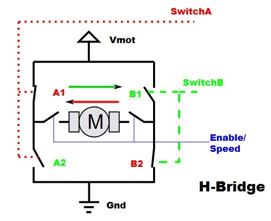
Motors are what make our robot move. To control the movement, we must control the motors. We want to be able to turn the motors on and off, change the direction they rotate, and slow them down or speed them up. The microcontroller (Babuino in our case) provides control signals, but we need something that can switch the current our motors need. Happily, there is one device that can provide all the desired capability. That device is known as an H-Bridge. Refer to the H-Bridge diagram; the gray thing in the middle is the motor that we want to control. Here’s how it works.
The microcontroller supplies the control signals SwitchA (which can be HI or LO), SwitchB (HI or LO) and Enable (HI or LO). SwitchA controls A1 and A2 in the diagram. When SwitchA is HI, A1 is closed and A2 is open. When SwitchA is LO, A1 is open and A2 is closed. SwitchB controls B1 and B2 in the same way. Enable works differently. When Enable is HI, both switches connected to it close; they open when it’s LO, thus turning the motor off. Let’s consider what happens when we make SwitchA HI, SwitchB LO and Enable HI. The two switches controlled by Enable close, and A1 and B2 also close. A2 and B1 remain open. So there is a complete circuit from Vmot (the voltage on the motors) to Ground through the motor. Current flows as shown by the red arrow. If we now turn off SwitchA and turn on SwitchB, A1 and B2 open while A2 and B2 close. We again have a complete circuit from Vmot to Ground, but this time the direction of current flow is reversed through the motor (as shown by the green arrow), so it reverses its direction of rotation.
If we turn on or off both SwitchA and SwitchB at the same time while Enable is HI, then the motor sees the same voltage on both sides. No current flows, but dynamic braking of the motor occurs and it comes to a stop more quickly than it would if only the Enable is switched LO (off). Sometimes this is important if you want to stop your robot quickly.
Great! We can control direction, but what about speed? That’s where the Enable signal comes in. Obviously, if we turn off the Enable, our current path is interrupted and the motor would stop. But what if we turn the Enable on and off very rapidly? As it turns out, if we do this rapidly enough, the motor never comes to a complete stop but just slows down. For example, if the switch is off half the time then the motor sees half power. This technique is known as Pulse Width Modulation (or PWM for short). A full discussion is beyond the scope of this Instructable (Google can help those interested) but the microcontrollers we use have special circuitry just for this. Babuino provides three signals to control each motor. For Motor A, these are named Motor A Left, Motor A Right, and Motor A PWM. Motor B has similar control signals. Left and Right are the signals we called SwitchA and SwitchB above, and thus control the motor direction. PWM is the Enable signal.
The H-Bridge does all the switching while handling enough current to run the motors. The particular H-Bridge we’ll use is the L293D. The L293D is a dual H-Bridge IC that has anti-kickback diodes built in. Anti-kickback diodes protect the H-Bridge from current spikes. The L293D is all we need to provide forward/reverse control for two small DC motors. Two of them can control four motors. The diagrams to follow show how to hook it up for our robotics breadboard.
For more detail: Build A Simple Robotics Breadboard Using Arduino
- Why build a custom robotics breadboard instead of using existing platforms?
Existing platforms often require expensive shop tools like band saws and involve soldering sensors in place, making changes difficult. - How can you reduce DC motor speed without reducing power?
Gears are used to reduce output speed while maintaining power, as simply reducing voltage greatly reduces available power. - What is the recommended method for securing wheels to the motor axles?
A small hole in the axle allows a screw to pass through a spacer and a cut plastic disk that is melted into the wheel to secure it. - Which leg of an LED should be connected to ground?
The shorter leg of a new LED is the one that goes to ground. - How do you identify the correct orientation for an electrolytic capacitor?
The leg nearest the side marked with minus signs must be connected to ground. - What component is used to control forward, reverse, and speed for the motors?
The L293D dual H-Bridge IC handles switching current to control direction and uses Pulse Width Modulation for speed. - What signals does the microcontroller send to the H-Bridge to stop the motor quickly?
Turning on both SwitchA and SwitchB at the same time while Enable is HI causes dynamic braking to stop the motor faster. - Can you use different types of microprocessors for the Babuino controller?
Yes, you can use either an actual Arduino clone or a simpler version with a built-in USB interface and additional hardware resources.