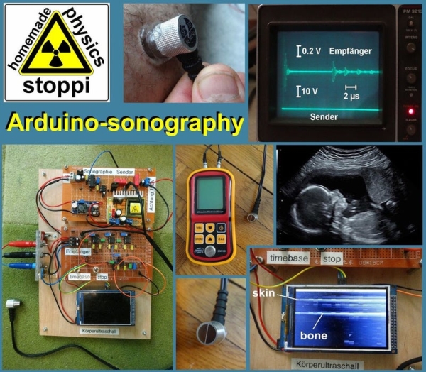
Summary of Body-ultrasound Sonography With Arduino
This article details a DIY ultrasonic sonography project inspired by medical imaging, using affordable components from eBay and AliExpress. The author successfully visualizes internal structures like bones using a 5 MHz transducer and an Arduino Due for data processing and display. The system generates high-voltage pulses to transmit sound waves and amplifies the returning echoes for visualization on a 320x480 screen.
Parts used in the Ultrasonic Sonography Project:
- GM100 paint thickness gauge or 5 MHz transducer
- Arduino Due microcontroller
- 320x480 pixel display li>Two 9V/1A power supplies for symmetric +9/GND/-9V supply
- Ultrasound gel
- 100V boost converter
- XL6009 boost-converter (12-15V)
- LM7805 voltage regulator
- Monoflop-IC 74121
- MOSFET-driver ICL7667
- IRL620 MOSFET
- C5 sockets
- AD811 operational amplifier
- LM7171 operational amplifier
- Various capacitors (1nF, 50pF, 0.1µF, 47µF, 20µF, 100nF, 1nF x5, 100nF x8)
- Various resistors (3kOhm, 10kOhm, 50Ohm, 68 Ohm, 330 Ohm, 820 Ohm, 470 Ohm, 1.5 kOhm, 1 kOhm, 100 Ohm)
- Potentiometers (10 kOhm, 10 kOhm x4, 100 kOhm)
- 1N4148 diodes
- 3.3V zener diode
My hobby and passion is to realize physics projects. One of my last work is about ultrasonic sonography. As always I tried to make it as simple as possible with parts you can get on ebay or aliexpress. So let’s take a look how far I can go with my simple items…
I was inspired by this a bit more complicated and more expensive project:
https://hackaday.io/project/9281-murgen-open-sourc…
Here are the parts you’ll need for my project:
the main parts:
- a gauge to measure the thickness of paint for 40 USD: ebay paint thickness gauge GM100
- or just the 5 MHz transducer for 33 USD: ebay 5 MHz transducer
- an arduino Due for 12 USD: ebay arduino due
- a 320×480 pixel display for 11 USD: 320×480 arduino display
- two 9V/1A power supplies for the symmetric +9/GND/-9V supply
- ultrasound-gel for sonography: 10 USD ultrasound gel
for the transmitter:
- a step-up-converter for the needed 100V for 5 USD: 100V boost converter
- a common step-up-converter supplying 12-15V for the 100V-boost-converter for 2 USD: XL6009 boost-converter
- a LM7805 voltage regulator
- monoflop-IC 74121
- mosfet-driver ICL7667
- IRL620 mosfet: IRL620
- capacitors with 1nF (1x), 50pF (1x), 0.1µF (1x electrolytic), 47µF (1x electrolytic), 20 µF (1 x electrolytic for 200V), 100 nF (2x MKP for 200V: 100nF20µF
- resistors with 3kOhm (0.25W), 10kOhm (0.25W) and 50Ohm (1W)
- 10 kOhm potentiometer
- 2 pcs. C5-sockets: 7 USD C5 socket
for the receiver:
- 3 pcs. AD811 operational amplifie: ebay AD811
- 1 pcs. LM7171 operational amplifie: ebay LM7171
- 5 x 1 nF capacitor, 8 x 100nF capacitor
- 4 x 10 kOhm potentiometer
- 1 x 100 kOhm potentiometer
- 0.25W resistors with 68 Ohm, 330 Ohm (2 pcs.), 820 Ohm, 470 Ohm, 1.5 kOhm, 1 kOhm, 100 Ohm
- 1N4148 diodes (2 pcs.)
- 3.3V zener diode (1 pcs.)
Step 1: My Transmitter- and Receiver-circuits
Sonography is a very important way in medicine to look inside the body. The principle is simple: A transmitter sends ultra-sonic-pulses. They spread out in the body, are being reflected by inner organs or bones and come back to the receiver.
In my case I use the gauge GM100 for measuring the thickness of paint layers. Though not really intended for looking inside the body i am able to see my bones.
The GM100-transmitter works with a frequency of 5 MHz. Therefore you have to create very short pulses with a length of 100-200 nanoseconds. The 7412-monoflop is able to create such short pulses. These short pulses go to the ICL7667-mosfet-driver, which drives the gate of an IRL620 (attention: the mosfet must be able to handle voltages up to 200V!).
If the gate is switched on, the 100V-100nF-capacitor discharges and a negative pulse of -100V is applied to the transmitter-piezo.
The ultrasonic-echoes, received from the GM100-head are going to a 3-stage amplifier with the fast OPA AD820. After the third step you’ll need a precision-rectifier. For this purpose I use an LM7171 operational amplifier.
Pay attention: I got the best results, when I shorten the input of the precision-rectifier with a dupont-wire-loop (? in the circuit). I don’t really understand why but you’ll have to check it if you try to reconstruct my ultrasonic-scanner.
Step 2: The Arduino-software
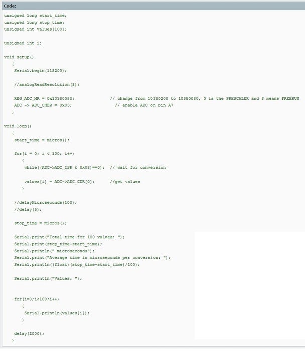
The reflected pulses have to be stored and displayed by a microcontroller. The microcontroller must be fast. Therefore I choose an arduino due. I’ve tried two different types of fast analog-read-codes (look at the attachments). One is faster (about 0.4 µs per conversion) but I got 2-3 times the same value when reading in the analog input. The other one is a bit slower (1 µs per conversion), but hasn’t the disadvantage of the repeated-values. I’ve chosen the first one…
There are two switches on the receiver-board. With those sitches you can stop the measurement and choose two different time-bases. One for measure-times between 0 and 120 µs and the other between 0 and 240 µs. I realized this by reading out 300 values or 600 values. For 600 values it takes twice the time, but then I take just every second analog-in-value.
The incoming echoes are being read with one of the analog-input-ports of the arduino. The zener-diode should protect the port for too high voltages because the arduino due can only read voltages up to 3.3V.
Each analog-input-value is then transformed into an value between 0 and 255. With this value a further grey-coloured-rectancle will be drawn on the display. White means high signal/echo, dark-grey or black means low signal/echo.
Here are the lines in the code for drawing the rectangles with 24 pixel width and 1 pixel height
for(i = 0; i < 300; i++)
{
values[i] = map(values[i], 0, 4095, 0, 255);
myGLCD.setColor(values[i], values[i], values[i]);
myGLCD.fillRect(j * 24, 15 + i, j * 24 + 23, 15 + i);
}
Read more: Body-ultrasound Sonography With Arduino
- What inspired this ultrasonic sonography project?
The project was inspired by a more complicated and expensive open-source project available on Hackaday. - How can I generate the short pulses required for the transmitter?
You must use a 7412-monoflop IC to create pulses with a length of 100-200 nanoseconds. - Which MOSFET is recommended for handling the required voltage?
An IRL620 MOSFET is used because it must be able to handle voltages up to 200V. - Why is a zener diode included in the receiver circuit?
The 3.3V zener diode protects the Arduino Due input port from too high voltages since the board only reads up to 3.3V. - How does the software visualize the received echoes?
Analog values are transformed into a range between 0 and 255 to draw grey-colored rectangles where white indicates high signal and black indicates low signal. - Can I adjust the measurement time range during operation?
Yes, two switches on the receiver board allow you to choose between time-bases of 0-120 µs and 0-240 µs. - What happens if I use the faster analog-read code?
The faster code yields about 0.4 µs per conversion but results in getting the same value 2-3 times repeatedly. - Is the GM100 gauge suitable for looking inside the body?
Although not intended for this purpose, the GM100 gauge allows the user to see bones when used for this project.