Summary of Bluetooth 4.0 HM-10 cc2541 Duplex
The article demonstrates bidirectional Bluetooth Low Energy (BLE) communication between two microcontrollers using HM-10 modules. It details configuring the modules via AT commands to establish a master-slave link and integrating them with Arduino or ATMEGA 328P boards for real-time data exchange, such as controlling servos via potentiometer inputs.
Parts used in the Bidirectional BLE Communication Project:
- Bluetooth 4.0 HM-10 Module
- CC2541 Chip (internal to HM-10)
- FTDI Cable
- Female to Male Wires
- ATMEGA 328P Microcontroller
- Arduino Board
- Attiny 44 Microcontroller
- Servo Motor
- Potentiometer
- LED
- Resistors and Capacitors
- Flexible Cable
In this example, I’ll show you how to use the cc2541 to communicate from one microcontroller to another in BOTH DIRECTIONS (BLE-HM-10).
Introduction
The HM-10 is a Bluetooth Low Energy (BLE) module for embedded systems that allows for wireless communication with BLE-capable devices (e.g. iPhone and iPad). It is fully configurable using a comprehensive and well-documented AT command set and supports transparent data communication via serial UART (default baud rate 9600bps).
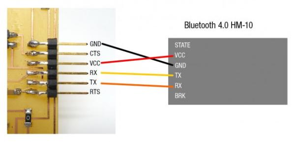
The Bluetooth 4.0 HM-10 is essentially a cc2541 breakout board, with LED pins, RX/TX, and a voltage regulator that converts 5v to 3.3v.
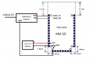
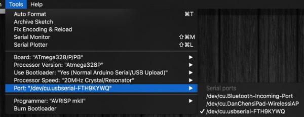
Setup with FTDI + Arduino Serial Monitor + AT Command
There are numerous things you can do with the Bluetooth 4.0 HM-10, but you must first set it up with an FTDI cable to understand what and how it works. Always use quality components even resistors & capacitors
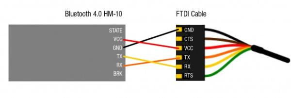
To connect to Bluetooth 4.0 HM-10 / BLE, you’ll need an FTDI cable and four female to male wires.
Open Arduino on your computer. Make certain that you choose the correct USB serial port. Open Serial Monitor and make sure the baud rate is set to 9600, which is the default.
Type in
AT+NAME? (NO SPACES IN AT COMMAND)
you should get OK+NAME:HMSoft
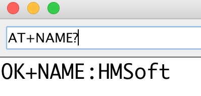
Check your connections if it says nothing. We can now communicate with BLE using the AT command, and the rest is straightforward.
More AT Commands can be found at the bottom of this post.
Sending & Receiving (Both Ways ) Setting the Master-Slave mode
This method allows you to turn on the device and have them talk to each other right away, without pairing or initialising… it’s fantastic. The information flows both ways.
First to begin, use AT Command AT+ADDR? to query the native MAC address.
Each BLE has its own MAC address, which is as follows: 20C38FF61DA1.
Use AT+CON[param1] and AT+ROLE[param1] to pair to another device.
Example
BLE A has Mac Address 11C11FF11DA1, I used AT+ADDR? to figure it out
BLE B has Mac Address 22C22FF22DA2, I used AT+ADDR? to figure it out
Send AT+CON22C22FF22DA2 to BLE A
Send AT+CON11C11FF11DA1 to BLE B
(Send the B address to A, A address to B)
Send AT+ROLE[0] to BLE A
Send AT+ROLE[1] to BLE B
(Doesn’t matter which one)
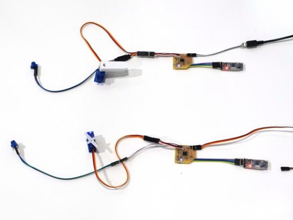
Now it’s ready to use on you ATMEGA 328P, Arduino or Attiny.
After connecting both BLE devices, the red light will remain solid. This should only take a few seconds.
Sending & Receiving Both Ways on ATMEGA 328P / Arduino
You can use the hardware serial to communicate with the ATMEGA 328P / Arduino. Software serial should allow Attiny 44 to communicate with BLE.
Data can communicate in both directions! Simply type Serial.println(whatever you want);
The ATMEGA 328Ps “analog reads” the potentiometer data and sends serial data via BLE to each other to turn their servos in the code below.
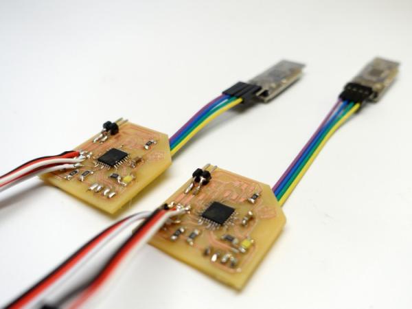
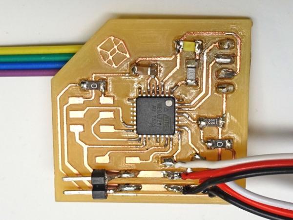
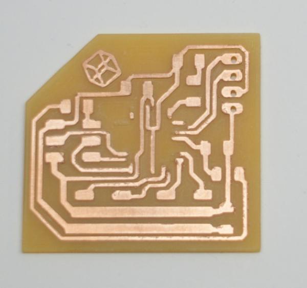
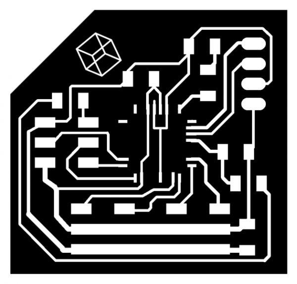
Example Board
To save space on my board, I removed the FTDI cable pads and uploaded my programme using ISP pins. This board is ULTRA compact because I want it to be part of my wearable project. You can order electronic components from it.
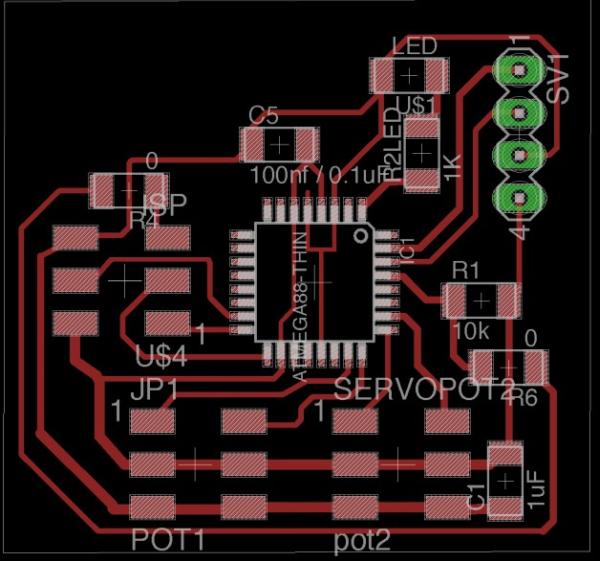
Because this needs to be wearable, I didn’t use any SMD male pins to save some vertical space.
Each of the microcontrollers listed below runs the same code! So, as soon as the BLE is turned on, it begins searching for the assigned address, which takes less than a second. The BLE’s solid RED LED indicator indicates that the connection has been established.
I have a flexible cable coming out of it to make it wearable and flat.

//receiving
int led = 3;           // the pin that the LED is attached to
#include
Servo myservo;  // create servo object to control a servo

//sending
int sensorValue = 0;
int presensorValue = 0;

void setup() {
  pinMode(led, OUTPUT);
  myservo.attach(A2);  // attaches the servo on pin 9 to the servo object
  myservo.write(90);              // tell servo to go to position in variable 'pos'
  delay(500);
  myservo.write(80);              // tell servo to go to position in variable 'pos'
  Serial.begin(9600);

}

void loop() {

  //receiving
  while (Serial.available() > 0) {
    int pos = Serial.parseInt();
    if (pos > 1 && pos < 180) {
      myservo.write(pos);              // tell servo to go to position in variable 'pos'
      //Serial.println(pos);
      analogWrite(led, 255);
    }
    sender();
  }
  sender();

  analogWrite(led, 10);


}


void sender() {

  // Sending
  // read the input on analog pin 0:
  //sensorValue = analogRead(A1);
  sensorValue = map(analogRead(A3), 0, 1024, 5, 175);


  //with noise reduction
  if (sensorValue == presensorValue  || sensorValue - 1 == presensorValue || sensorValue + 1 == presensorValue) {
  }
  else {
    Serial.println(sensorValue);
  }
  presensorValue = sensorValue;

  delay(50);

}
-
What is the default baud rate for the HM-10 module?
The default baud rate is 9600bps. -
How do you configure the HM-10 to communicate via serial UART?
You must use an FTDI cable and set the Serial Monitor baud rate to 9600 to send AT commands. -
Which command queries the native MAC address of a BLE device?
The command AT+ADDR? is used to query the native MAC address. -
How do you set one device as the master and the other as the slave?
Send AT+ROLE[0] to one device and AT+ROLE[1] to the other device. -
What indicates that the connection between two BLE devices has been established?
A solid red LED light on the BLE device indicates the connection is established. -
Can this setup work with an Attiny 44 microcontroller?
Yes, software serial should allow the Attiny 44 to communicate with the BLE module. -
How does the code handle noise when reading sensor values?
The code compares the current sensor value with the previous value and only sends data if they differ significantly. -
What voltage regulator function does the HM-10 board provide?
The board includes a voltage regulator that converts 5v to 3.3v.