Now I think just about everybody has a binary clock and here’s my version. What I enjoyed was that this project combined some woodwork, programming, learning, electronics and perhaps just a little artistic creativity.
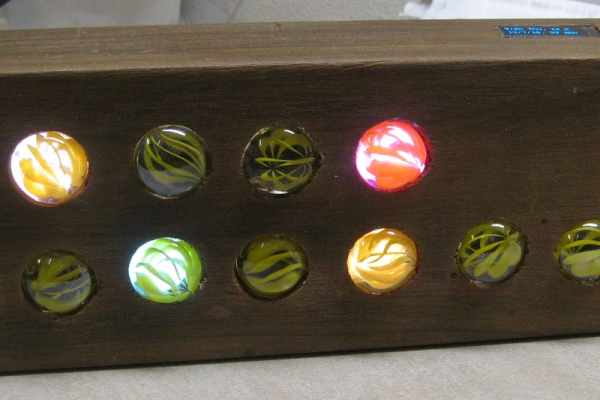
It shows time, month, date, day of week, temperature and humidity on the marble display in a binary form – an illuminated marble is “on” and represents a digit. All this info is also displayed on an oled display in a conventional way. There is provision to set the time from the computer, daylight saving is easily adjusted and there is an ability to “bump” the time to the top of the hour by using an external radio signal or other accurate source.
Many of the binary clocks you see use separate columns for minute, tens of minutes, hours and tens of hours, so you assemble the time by reading each individual column which represents a number and so a single digit of the time. Mine is different because you add together the binary values for minute in one string and hours in another string. The pictures will help, but the minutes string is six bits, from the rightmost end which is the least significant to leftmost end which is the most significant representing one, two, four, eight, sixteen and thirty two minutes. You arithmetically add the individual values. The Hours is likewise, one to eight hours.
Various colours indicate what function is currently being displayed. Magenta for month, yellow for date, green for day of week, red for temperature, blue for humidity and random colours for time. The display cycles through all functions and the delay pause can be set in the code.
The clock looks really cool at night in a darkened room although it’s hard to take good photos that show the intensity.
Step 1: Clock Program Features
A few comments on some software features of the clock.
Time setting: Many of the Arduino examples which use an rtc are casual in how they set the time. Very often they use the compile time of the sketch to set the rtc if it is not already set. Since you don’t know how long the compile and download will take this is clumsy, also if the clock has been previously set then the time is not updated.
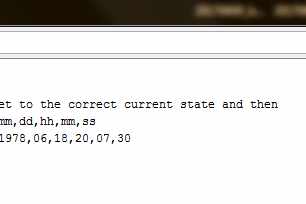
I have put a flag (KBSetTime = true | false) within the code that will, if set upon download, cause a serial window to open and prompt for time entry. The time is precisely set to the rtc when enter is pressed.
Accuracy: The DST3231 module has a specified accuracy of +/- 2 ppm, which is about 1 min per year at normal temperatures. To allow for correction of this drift there is a “bump” button provided. The idea is that when you hear the time source signal pips that are broadcast over the radio the bump button is pressed and the time is adjusted to the “top of the hour”. To prevent wandering fingers I have limited this feature to only be active in the range of five to or five past the hour.
Daylight Saving: is problematic! The clock isn’t sync’d to any external source that is DST aware, so there’s no way to automatically adjust , like say a phone would do due to it’s connection to a networke tower. In older versions of Windows they just use a file which has dates in it that specify when the change should occur, for this you need to know, in advance and with certainty the change dates – how far do we go, what is the expected life of the clock, what if we move jurisdictions? etc etc Other approaches rely on a fixed specification eg 2nd Sunday in March, but this has problems too – not every locality adjusts at the same time, special events may move this “fixed” change point. For these reasons I decided on a different approach that lets the user easily make the adjustment – a slide switch is set to specify moving into or out of daylight saving, then a push button is pressed. This will either add or subtract exactly an hour to the current time. The accuracy of dates is maintained in case you do it at say 23:45hrs.
Expansions: As is the clock displays in 12h format, with four leds for hours the max is 8+4+2+1 = 15, so you could add an extra led if 24h hour format is desired. Alternatively you could add a way to indicate am or pm. The software libraries and interface to the clock module will all allow these easily should it be desired.
Step 2: Bits & Bobs – the Pieces
The Arduino world has an array of interesting bits, all remarkably cheap from ebay, ali barber and so on. There’s lots of guidance and advice available too. Here’s what I used;
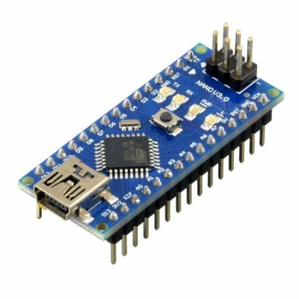
- Nano arduino, cheap, powerful, educational – this project ends up using about 80% of the code space
- DS3231 – real time clock module that maintains time, 2 ppm accuracy that is about 1 min / year
- SSD1306 oled display, 128 x 32 pixels
- WS8212 leds – serially controlled leds, 3 wire, individual led colour set by 3 byte RGB string
- DHT22 – temperature and humidity module. A capacitive humidity sensor and a thermistor
- miscellaneous switches, push buttons – power supply with connector to fit Arduino
It might have been nicer to use capacitive touch switches in place of push buttons. An example would be TTP223
A note on the DS3231 rtc module: If you use this with a lithium button cell like a CR2032 (and most people will) you need to cut the battery charge trace on the module. An internet search will reveal info and reasons on this. The picture above illustrates the trace to be cut.
Step 3: Wiring
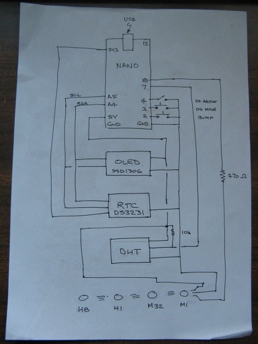
The diagram shows the wiring connections.
Step 4: Code
The code is presented here and you can just download and use it. You need the Arduino environment installed.
Hopefully it is commented sufficiently to allow it to be followed and modified by anyone with some Arduino skills.
The Arduino world has many libraries where smart folk make it easy for the rest of us to use devices. There’s no point reinventing the wheel so I made use of the following libraries;
- TimeLib.h – for use and management of time functions
- DS3223RTC.h – for access to the rtc module
- Adafruit_NeoPixel.h – for using the serial leds
- DHT.h – for the humidity and temperature sensor
- Streaming.h – for easy interaction with the serial window
- U8glib.h – for the Oled display
the IC2 bus is used, this is inbuilt into the Arduino, the rtc and oled modules and associated libraries – it’s all transparent to the use because of the libraries mentioned above
Interrupts. These are used for the bump to hour and daylight saving adjust routines. The former because it needs to happen in a time critical manner and the latter because it will be infrequently used.
The pause delay for the display times for each display feature can be adjusted by the show_xxxx_delay constants. eg the red temperature leds being displayed is set to 4000 ms or 4 seconds by the line
const unsigned long show_temp_delay = 4000;
Variations of colour can be made by editing the lines – it’s just three hex values each 00..ff for RGB
#define Yellow leds.Color(0xff, 0xff, 0x00) // colour for day display
Step 5: Woodwork
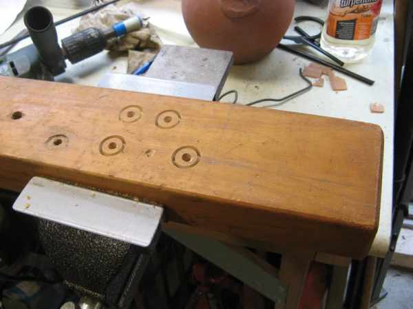
I started with a piece of pine that was in the garage, cut to length as needed. The marbles sit in recessed pockets, so from the front face you drill a larger hole the diameter of the marble to the depth you want and then drill a smaller hole to allow the light to see the back of the marble. With the holes drilled I used a plunge router to carve out a pocket from the rear to house the electronics.
I cut a small recess on the top surface so the Oed display would sit flush.
The back piece is cut to size and provision made for the buttons and DHT sensor.
I stained the pine with a homemade stain mix and applied a coat of wax to give a satin finish
Source: Binary LED Marble Clock