Part 1: Build an Arduino on a Board
Part 2: Build the motor-controller & body
Part 3: Adding Sight and Touch
Part 4: Blinging up the BaW-Bot
Part 5: Taking it to the Next Level
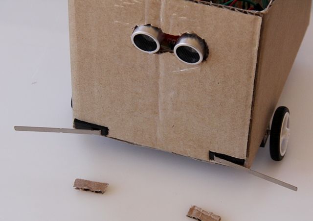
In this instructable, we’ll be giving our Bot some freedom by adding sensors to keep it safe. We’ll be adding an ultrasonic sensor (“eyes”) as well as 2 lever microswitches (“whiskers”). We’ll also be building a “leash” so that we can keep it out of trouble while we develop the bot.
Step 1: The Parts
1 x IR Receiver (38KHz)
1 x Household Infrared Remote Control (TV / stereo / iPod / etc.)
1 x Ultrasonic Range Sensor
2 x Lever Snap Action switches
Connector wires
2 x 10k Ohm resistors
Step 2: Rein the Bot In
Help from Ken
Ken Shirriff has written a few great blogs on getting IR working on an Arduino (check out http://www.arcfn.com/), and has also written a very useful library. We’ll use that library for this instructable (thanks Ken!) – even though we won’t use close to all the functionality it offers.
To begin, download the library from the link on Ken’s page on his Infrared Remote Library and unzip it into your Arduino folder:
arduino\libraries.
If you’re using version 1.0 or higher of the Arduino IDE, you’ll need to edit the file “IRRemoteInt.h” and change the line:
#include <WProgram.h>
to
#include <Arduino.h>
Then restart the IDE.
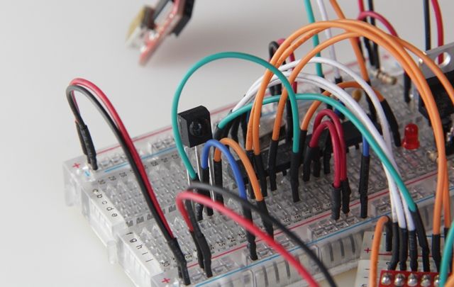
Step 3: Connect the IR Receiver
Remove the breadboards from the body, so we can work on them more easily. Make sure you disconnect the motor power supply – we don’t want the Bot to run away from us while we’re testing.
Connect the IR Receiver
Refer to the fact sheet for the IR Receiver – you’ll see it has 3 pins – Vs, GND and OUT. For this test, mount the IR Receiver on the Arduino breadboard, and connect:
- Vs to the +ve power rail
- GND to the GND power rail
- OUT to pin 12 (i.e. physical pin 18 on the ATmega chip).
This is pretty self-explanatory – the module will be powered by Vs and GND, and will send a signal to Pin 12 when it receives an IR signal.
Step 4: Test the IR Receiver
Upload the sketch below using the FTDI breakout board. This was written by Ken, and simply prints out any IR codes the sensor receives, to the Serial monitor (I have modified to print decimal instead of Ken’s original hex).
Test a few Remotes
Once the sketch is uploaded, start the Serial Monitor in the Arduino IDE (Tools, Serial Monitor).
Point a number of remote controls at the sensor, and watch what comes out on the serial monitor when you press their various buttons. You should see output similar to the image above. Do you notice that each button generates a slightly different code? These unique codes will allow us to write a sketch that reacts to a particular code – i.e. a particular button on a remote.
In some cases one button might generate multiple codes, or holding a button down could result in a single code repeating – we’ll ignore these for this project.
Copy the Code for your chosen button
Now that you’ve seen how the codes appear, press the button that you want to use to stop/start the BaW-Bot. Now copy and paste the code from the Serial Monitor into a temporary test document – we’ll need it later.
For my bot, I used the play/pause button on my iPod docking station remote. This generated 2 codes, so I just took the first one: “2011265621”
Now let’s put this code to good use.
 Part3-1 – Test_IR_Codes.txt566 bytes
Step 5: Get Things Under Control
Before we continue, let’s see how the remote works with your bot. Put the boards back into the BaW-Bot, and download the sketch below. This is a very simple sketch that moves and turns the bot as you press your chosen button on the remote.
For more detail: BaW-Bot Part 3: Adding Sight and Touch to the Bot