Summary of Basic Projects using chipKIT Uno32
This article highlights the Digilent Basic I/O Shield, an add-on board for chipKIT Uno32, uC32, and Max 32 microcontrollers. It simplifies prototyping by integrating multiple components, eliminating the need for complex wiring. The post demonstrates four projects: sequential LED arrays, potentiometer-controlled LED counts, RGB analog strip fading, and a combined system using switches, pots, and RGB strips. These examples showcase how the shield enables rapid development of creative electronics projects with minimal setup time.
Parts used in the ChipKIT Basic I/O Shield Projects:
- chipKIT Uno32
- chipKIT uC32
- chipKIT Max 32
- Basic I/O Shield
- MPIDE software
- 8 LEDs
- 10K Potentiometer
- Analog RGB Strip
- Individual FET channels
- 12V Power Supply
- On-off switch (S4)
- Control switches (S1-S3)
Happy Tuesday, everyone! I tend to get excited about products that enable beginners to be really creative, and today’s product highlight is one I think is worth getting excited about!
A few things that I really like about the shield:
The shield is an add-on board that was designed to be used with the chipKIT Uno32, the uC32, or the Max 32.
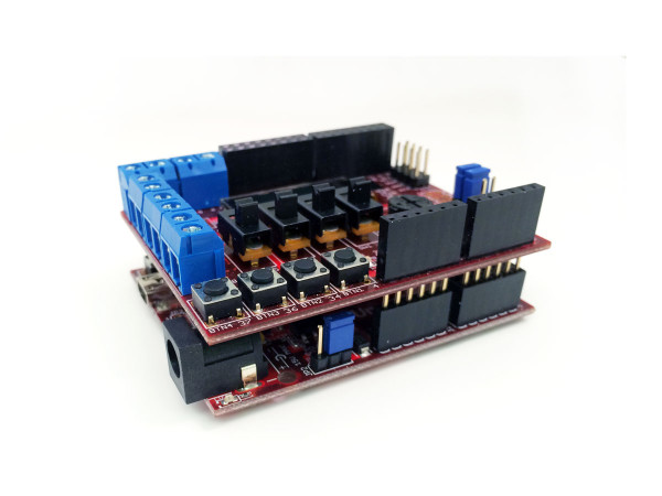 Once you connect the Basic I/O Shield to the chipKIT board of choice and download MPIDE (referenced in the video), then a world of projects are instantly at your fingertips. This is because of all of features that are built-into the shield.
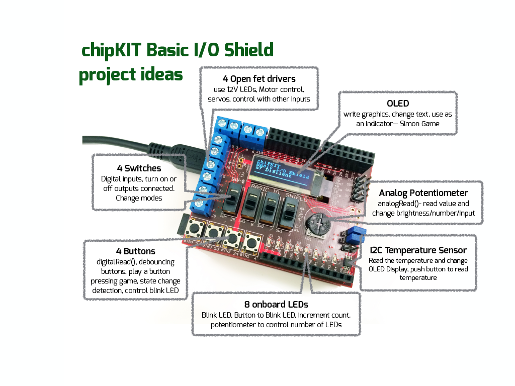 Just a few project ideas using the multiple I/Os on the shield. Combining them makes even more powerful projects!
Perhaps the best part about the Basic I/O Shield is that you don’t have to spend time wiring up all of the individual components. This is great for teachers who have limited course time, if you are doing a workshop focused on the programming, or if you want to spend your time wiring up something non-traditional… like 12V Analog LEDs (see the end of post for demo)!
Here are a few projects that we’ve done with the I/O Shield, but we’d love to see other project ideas!
Having the 8 LEDs Run back and forth in sequence (using an Array):
/*Arrays

 Demonstrates the use of  an array to hold pin numbers
 in order to iterate over the pins in a sequence.
 Lights multiple LEDs in sequence, then in reverse.

 Unlike the For Loop tutorial, where the pins have to be
 contiguous, here the pins can be in any random order.

 The circuit:
 * on an Arduino and chipKIT uno32 LEDs from pins 2 through 7 to ground
 * on the chipKIT I/O Expander Shield it's pins 26-33

 created 2006
 by David A. Mellis
 modified 5 Jul 2009
 by Tom Igoe  modified by Larissa Swanland Digilent Inc-2014
This example code is in the public domain.

 http://www.arduino.cc/en/Tutorial/Array
 */

int timer = 100;           // The higher the number, the slower the timing.
int ledPins[] = {
  33, 32, 31, 30, 29, 28, 27, 26 };       // an array of pin numbers to which LEDs are
 attached
int pinCount = 8;           // the number of pins (i.e. the length of the array)

void setup() {
  int thisPin;
  // the array elements are numbered from 0 to (pinCount - 1).
  // use a for loop to initialize each pin as an output:
  for (int thisPin = 0; thisPin < pinCount; thisPin++)  {
    pinMode(ledPins[thisPin], OUTPUT);
  }
}

void loop() {
  // loop from the lowest pin to the highest:
  for (int thisPin = 0; thisPin < pinCount; thisPin++) {
    // turn the pin on:
    digitalWrite(ledPins[thisPin], HIGH);
    delay(timer);
    // turn the pin off:
    digitalWrite(ledPins[thisPin], LOW);

  }

  // loop from the highest pin to the lowest:
  for (int thisPin = pinCount - 1; thisPin >= 0; thisPin--) {
    // turn the pin on:
    digitalWrite(ledPins[thisPin], HIGH);
    delay(timer);
    // turn the pin off:
    digitalWrite(ledPins[thisPin], LOW);
  }
}
Using the Analog Potentiometer to Change the Number of LEDs:
/*Digilent Inc.
Larissa Swanland 2014
Code written to use with chipKIT Uno32/UC32 + the IO Expander Shield
focus with 10K Potiometer and 8 LED's
to see the pin-outs please look at page 8 in IO Expander reference guide:
https://digilentinc.com/Data/Products/CHIPKIT-BASIC-IO-SHIELD/chipKIT%20Basic%20IO%20Shield
_rm.pdf*/

const int potPin= A0; //Pin that the 10K Pot is attached to

//LED Outputs using an Array, please see Array Code for example
int i;
int led[] = {33, 32, 31, 30, 29, 28, 27, 26 };      // an array of pin numbers to which
 LEDs are attached

//variables that will change:
int potRead= 0;
int potVal= 0;  //Mapped Value of Pot
int lastPot=0; //last value of Pot Stored


void setup(){
  pinMode(potPin, INPUT);  // declare Pot as input
  //intialize the LED pins
  for (int i=0; i < 9; i++){
    pinMode(led[i], OUTPUT);
  }
  Serial.begin(9600);
}

void loop(){
  potRead=analogRead(potPin);            //read Analog Value attached to Pot
  potVal= map(potRead, 0, 1023, 0, 8);   //map the value from 0-1023 to 0-7
 (coincides with LED Array)

                                         //compare old reading to new reading
  if (potVal!= lastPot) {                //if current value is different from old
    lastPot = potVal;                    //then store the new value
    Serial.print(potVal);                //for debugging using Serial monitor
    for (int i=0; i<potVal+1; i++){
      digitalWrite(led[i],HIGH);
    }
  } else {
    for(int i= potVal-1; i>=0; i--){
      digitalWrite(led[i], LOW);
    }
  }

}
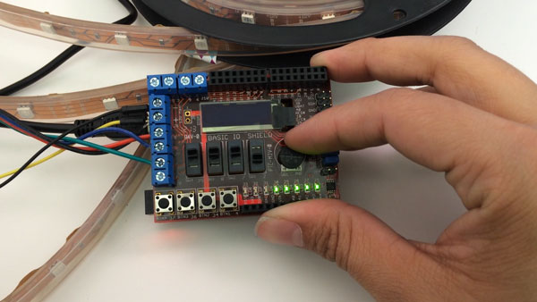
RGB Analog Strip:

/*Digilent Inc.
Larissa Swanland 2014- Fade colors for RGB Strips
Connect Analog RGB to individual FET channels and power to shared 12V Power Supply
(see photo)*/
#define REDPIN 5
#define GREENPIN 3
#define BLUEPIN 9

#define FADESPEED 5     // make this higher to slow down

void setup() {
  pinMode(REDPIN, OUTPUT);
  pinMode(GREENPIN, OUTPUT);
  pinMode(BLUEPIN, OUTPUT);
}


void loop() {
  int r, g, b;

  // fade from blue to violet
  for (r = 0; r < 256; r++) {
    analogWrite(REDPIN, r);
    delay(FADESPEED);
  }
  // fade from violet to red
  for (b = 255; b > 0; b--) {
    analogWrite(BLUEPIN, b);
    delay(FADESPEED);
  }
  // fade from red to yellow
  for (g = 0; g < 256; g++) {
    analogWrite(GREENPIN, g);
    delay(FADESPEED);
  }
  // fade from yellow to green
  for (r = 255; r > 0; r--) {
    analogWrite(REDPIN, r);
    delay(FADESPEED);
  }
  // fade from green to teal
  for (b = 0; b < 256; b++) {
    analogWrite(BLUEPIN, b);
    delay(FADESPEED);
  }
  // fade from teal to blue
  for (g = 255; g > 0; g--) {
    analogWrite(GREENPIN, g);
    delay(FADESPEED);
  }
}
Combining Switches + Potentiometer + Analog RGB Strips:
/*Digilent Inc
Larissa Swanland 2014
S4- is the on-off switch
S1-3 are the switches that control the channel on the RGB LEDs
The Analog Pot will control brightness*/

const int potPin= A0; //Pin that the 10K Pot is attached to
const int red = 5; // Pin 3 when LED Strip is connected
const int blue= 3; // Pin 5 when LED Strip is connected
const int green= 9; // Pin 6 When LED Strip is connected
const int sw1= 35;
const int sw2= 8;
const int sw3= 7;
const int sw4= 2;

int s1,s2,s3,s4;
int potRead= 0;
int potVal=0;  //Mapped Value of Pot-- intensity
int lastPot=0; //last value of Pot Stored

void setup(){
  pinMode(sw1, INPUT);
  pinMode(sw2, INPUT);
  pinMode(sw3, INPUT);
  pinMode(sw4, INPUT);

  pinMode(potPin, INPUT);  // declare Pot as input

  pinMode(red, OUTPUT);
  pinMode(blue, OUTPUT);
  pinMode(green, OUTPUT);

  Serial.begin(9600);
}

void loop(){
  //read the switch values
  s1= digitalRead(sw1); //red
  s2= digitalRead(sw2); //green
  s3= digitalRead(sw3); //blue
  s4= digitalRead(sw4); //on or off
  potRead=analogRead(potPin); //read Analog Value attached to Pot
  potVal=map(potRead, 0, 1023, 0, 256); //map the pot to the value of RGB Brightness

   if(potVal!=lastPot){
   lastPot= potVal;
   Serial.print(potVal);}

  if(s4==0)// the last switch is on
 {
  analogWrite(red, 0);
  analogWrite(green,0);
  analogWrite(blue, 0);
 }else{
   analogWrite(red, s1*potVal);
   analogWrite(green,s2*potVal);
   analogWrite(blue,s3*potVal);
 }
  Combine all of the sketches together!
}
/*Digilent Inc
Larissa Swanland 2014
S4- will make the LEDs cycle through a routine (there is a slight delay)
S1-3 are the switches that control the channel on the RGB LEDs
The Analog Pot will speed of the cycle*/

const int potPin= A0; //Pin that the 10K Pot is attached to
const int red = 5; // Pin 3 when LED Strip is connected
const int blue= 3; // Pin 5 when LED Strip is connected
const int green= 9; // Pin 6 When LED Strip is connected
const int sw1= 35;
const int sw2= 8;
const int sw3= 7;
const int sw4= 2;

int s1,s2,s3,s4;
int potRead= 0;
int potVal=0; //Mapped Value of Pot-- intensity
int lastPot=0; //last value of Pot Stored
int fadespeed=1; //fadespeed

void setup(){
pinMode(sw1, INPUT);
pinMode(sw2, INPUT);
pinMode(sw3, INPUT);
pinMode(sw4, INPUT);

pinMode(potPin, INPUT); // declare Pot as input

pinMode(red, OUTPUT);
pinMode(blue, OUTPUT);
pinMode(green, OUTPUT);

Serial.begin(9600);
}

void loop(){

//read the switch values
s1= digitalRead(sw1); //red
s2= digitalRead(sw2); //green
s3= digitalRead(sw3); //blue
s4= digitalRead(sw4); //on or off
potRead=analogRead(potPin); //read Analog Value attached to Pot
potVal=map(potRead, 0, 1023, 0, 256); //map the pot to the value of RGB Brightness

while(potVal!=lastPot){
lastPot= potVal;
Serial.print(potVal);
}
if (s4==1)// the last switch is on
{

fade();

}else{
analogWrite(red, s1*potVal);
analogWrite(green,s2*potVal);
analogWrite(blue,s3*potVal);
}
}

void fade(){
int r, g, b;
fadespeed= 255/potVal;

// fade from blue to violet
for (r = 0; r < 256; r++) { analogWrite(red, r); delay(fadespeed); } // fade from violet
 to red for (b = 255; b > 0; b--) {
analogWrite(blue, b);
delay(fadespeed);
}
// fade from red to yellow
for (g = 0; g < 256; g++) { analogWrite(green, g); delay(fadespeed); } // fade from yellow
to green for (r = 255; r > 0; r--) {
analogWrite(red, r);
delay(fadespeed);
}
// fade from green to teal
for (b = 0; b < 256; b++) { analogWrite(blue, b); delay(fadespeed); } // fade from teal to
blue for (g = 255; g > 0; g--) {
analogWrite(green, g);
delay(fadespeed);
}
}
- What is the Basic I/O Shield designed for?
It is an add-on board designed to be used with the chipKIT Uno32, uC32, or Max 32. - How do you enable project creation with this shield?
You must connect the shield to a chipKIT board and download MPIDE software. - Why is this shield beneficial for teachers or workshops?
It saves time because users do not have to wire up individual components. - Which pins are used for the 8 LEDs on the I/O Expander Shield?
The LEDs are attached to pins 26 through 33. - How does the potentiometer code control the number of LEDs?
It maps the analog value from 0-1023 to a range of 0-7 to match the LED array length. - What hardware is required for the RGB Analog Strip project?
It requires connecting the analog RGB to individual FET channels and a shared 12V power supply. - Which switch controls the on-off state in the combined project?
Switch S4 acts as the on-off switch for the entire system. - What function does the analog potentiometer serve in the combined project?
It controls the brightness intensity of the RGB LEDs. - Can the pin numbers in the array code be contiguous?
No, unlike the For Loop tutorial, the pins can be in any random order. - How is the speed of the color cycle adjusted?
The analog potentiometer value is mapped to adjust the fade speed variable.