Summary of Arduino Sous-Vide Cooker
This article details how to build an Arduino-controlled sous-vide cooker for precise temperature regulation. By combining a microcontroller, temperature sensor, and relay system with a slow cooker, users can automate the water bath process. The guide covers constructing a waterproof probe, wiring the circuit including AC connections, and optionally adding an LCD display for monitoring.
Parts used in the Arduino Sous-Vide Cooker:
- Arduino microcontroller (Uno or similar)
- Thermistor or temperature sensor
- Aluminum or copper tube (3/16" diameter, 6" long)
- Shrink tubing
- Clear silicone caulk
- Relay controller
- 9V battery or 9V power adapter
- AC outlet
- AC power cord with bare leads
- Project box (e.g., cigar box)
- Crock-Pot or slow cooker with "On" setting
- LCD display (optional)
- Various hookup wires
- Ziploc bags or vacuum sealer
- 10KOhm resistor
Sous-vide cooking allows you to precisely control the temperature of cooked food (how “doneness” is measured) by immersing it in a carefully controlled water bath. It’s possible, but seriously difficult, to do this just with a thermometer and a pot on the stove… but if you have an Arduino do all the hard work for you, you can literally “set it and forget it.”
Materials:
– Arduino microcontroller (I use the Uno… any will do)
– thermistor, or other temperature sensor (I used this one from Sparkfun )
– 3/16″ diameter aluminum or copper tube, about 6″ long
– shrink tubing
– clear silicone caulk
 – relay controller (this one from Sparkfun is nice, but you can make your own pretty easily)
– 9V battery or 9V power adapter
– AC outlet
– AC power cord with bare leads
– project box (I used an old cigar box)
– Crock-Pot or similar slow cooker (must have “On” setting… the dumber, the better)
– display (optional, but nice to have)
– various hookup wires
– Ziploc bags or vacuum sealer Disclaimer: this project involves household current, which is dangerous if you don’t know what you’re doing. If you’ve never dealt with household current and don’t want to mess with it, go with the Powerswitch Tail II from the Makershed or Sparkfun instead of using the relay controller and AC outlet. Please be careful, and don’t hurt yourself.
Step 1: Make your temperature probe
First we need to put together our temperature probe. This is basically our sensor (the thermistor), a protective tube, and a length of wire. The probe will stay in the water bath when you’re cooking, so the wire has to be long enough to reach. First we solder the sensor to however many wires your sensor needs; our thermistor needs two wires. Use some shrink tubing to keep the leads insulated. Next we’re going to protect the sensor so the water bath doesn’t affect our readings. Use an aluminum or copper tube (both are great thermal conductors) big enough fit your temp sensor. Seal one end of the tube with silicone caulk (or hot glue if you’re impatient, but silicone would be better). When that has cured/solidified, slide the temp sensor into the tube as far as it will go, then fill the open end with more silicone/hot glue to seal it up. Use some shrink tubing at that end for good measure.
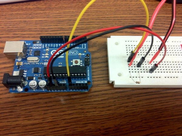
Step 2: Wire everything up. First the sensor…
Step 3: … next the relay controller…
Step 4: … then the AC outlet…
Connect the neutral lead of the AC power cord to the neutral pole of the AC outlet. Most outlets will have the poles labelled “Hot” or “Neutral”, but it’s easy enough to figure out if you’re not sure (in American outlets, small slot is Hot, large is Neutral, circular is ground). Definitely connect the ground lead to the ground pole on the outlet if your power cord has one… it will protect you (to some degree) if there are any shorts. Connect the hot lead of the power cord to one of the leads on your relay controller (doesn’t matter which one), and connect the other lead to the hot pole of the AC outlet. Again, if you don’t want to mess with wiring that will be connected to household current, buy a Powertail instead. Having nicely cooked food isn’t worth getting electrocuted ‘if you don’t know what you’re doing.
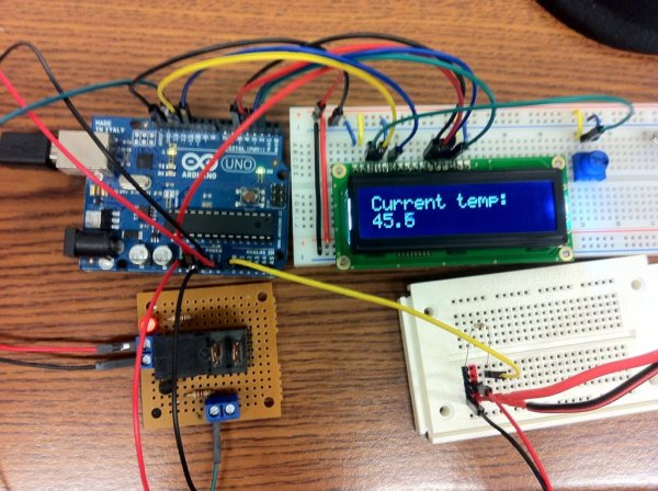
Step 5: … and finally the display (if you want one).
– LCD RS pin to digital pin 12
– LCD Enable pin to digital pin 11
– LCD D4 pin to digital pin 5
– LCD D5 pin to digital pin 4
– LCD D6 pin to digital pin 3
– LCD D7 pin to digital pin 2
– LCD R/W pin to ground
– 10K resistor: ends to +5V and ground wiper to LCD VO pin (pin 3)
For more detail: Arduino Sous-Vide Cooker
-
How do you make the temperature probe?
Solder sensor wires to the thermistor, insulate with shrink tubing, seal one end of a metal tube with silicone caulk, insert the sensor, and seal the other end. -
Can you use 5V instead of 3.3V for the thermistor setup?
Yes, you can use 5V, but if using a display, you might need the slot for that connection. -
Does the project involve dangerous household current?
Yes, the project involves household current which is dangerous if you do not know what you are doing. -
What is the best way to connect the AC hot lead?
Connect the hot lead of the power cord to one lead on the relay controller and the other lead to the hot pole of the AC outlet. -
How do you wire the LCD display pins?
Connect RS to pin 12, Enable to pin 11, D4 to pin 5, D5 to pin 4, D6 to pin 3, D7 to pin 2, R/W to ground, and use a 10K resistor between +5V and ground with the wiper to VO. -
What should you do if you do not want to mess with household current?
You should buy a Powertail from Makershed or Sparkfun instead of using the relay controller and AC outlet directly. -
Why is aluminum or copper tube used for the probe?
Both materials are great thermal conductors needed to protect the sensor while ensuring accurate readings.