Summary of Autonomous Control of RPM of Engine Using Feedback System From a IR Based Tachometer
This project automates engine RPM control by using an IR tachometer feedback loop: a user-entered desired RPM drives a stepper motor that adjusts the scooter throttle via a belt-driven pump coupling. An Arduino Mega reads the IR sensor, displays values on an LCD, takes keypad input, and commands an L293D-driven 5-wire stepper to reach and maintain the set RPM.
Parts used in the Autonomous Control of RPM of Engine Using Feedback System From a IR Based Tachometer:
- Arduino Mega 2560 microcontroller
- L293D motor driver IC (or breakout board)
- 16 X 2 LCD display
- Infrared/proximity sensor (STL015V1.0_IR_Sensor)
- Unipolar 5-wire stepper motor (12 V)
- 4 X 4 Keypad
- 220 ohm resistors
- 1000 ohm resistors
- 10k potentiometer
- Connector wires / colored wires / wire stripper
- Breadboards
- 12V battery (to power stepper motor)
- 5V supply (to power Arduino)
There is always a need for automating a process,be it a simple/monstrous one.I got the idea to do this project from a simple challenge that i faced while finding methods to water/irrigate our small piece of land.The problem of no current supply lines and costly generators (to operate our pump) added to the difficulty.

So what we decided to do is device a method which would be cheap and easy to use,even by a worker.We decided to mount the pump on our old scooter(running condition) and run it using the shaft of the scooter wheel.All fine and good,we made the mechanical assembly and the belt drive and tested it,and it was a success.
But another problem was that,when the motor was running,a person always had to be near the scooter to monitor the RPM,and manually adjust it using throttle.So this project was made by us so that the worker can set the desired RPM he wants to make the engine run,and attend to other work in the farm.
The setup consists of :
- A IR based tachometer(to measure RPM).
- A keypad to enter the RPM.
- A LCD display to show the monitored RPM and current RPM.
- A Stepper motor to increase/decrease the throttle.
- Finally,a micro-controller to manage all these processes.
Step 1: Arranging the Required Parts
Previously,I just gave the overview of what the components would be.
The actual components required are:
- A micro-controller(I used an Arduino Mega 2560).
- A L293D motor driver IC(or a breakout board will do).
- A 16 X 2 LCD display.
- An infrared/proximity sensor (model number is STL015V1.0_IR_Sensor)
- A uni-polar stepper motor ( I used a 5 wire stepper motor,12 V).
- A 4 X 4 Keypad.
- Couple of 220 ohm,1000 ohm resistors.
- A 10k potentiometer.
- Connector wires,colored wires,stripper.
- Breadboards.
- A 12V battery to power the stepper motor.
- A 5V supply to power Arduino.
And thats all you need to get started,folks!
Step 2: Overall Flow of Process
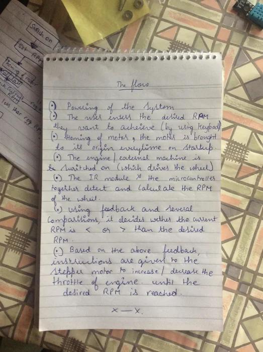
The flow of the process is as follows:
- The setup is switched on and wait till calibration of all device is done.
- The user shall input the required RPM using Keypad.
- The homing of the motor takes place.This is usually done so that a constant reference point is dictated to the motor so that when the setup is switched on,the initial position of motor is always constant and taken as reference point.
- Switch on the engine/any machine which shall rotate a wheel.
- The measurement of the RPM takes place and it displays on the LCD.
- This is where the feedback system comes into picture.If the detected RPM is less than the desired RPM,the stepper motor steps so that it increases the throttle
- If the detected RPM is more than the desired RPM,the stepper motor steps so that it decreases the throttle.
- This process takes place until the desired RPM is reached,when reached,the stepper stays still.
- The user can switch off the system if required using a master switch.
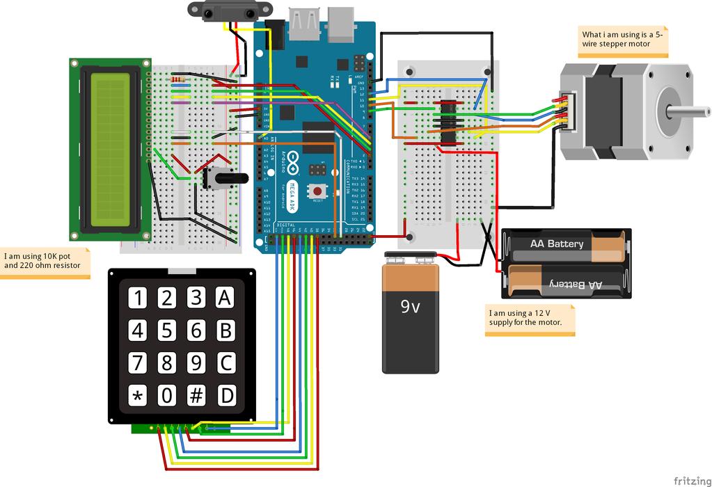
Step 3: Making the Required Connections
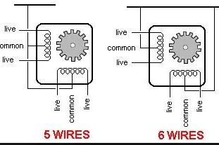
- Connections for the stepper motor:
Since i am using a 5-Wire stepper motor,4 wires are for energizing the coils and the other one is connected to the ground.It is not always necessary that the order of the 4 wires coming out of the motor is the same order to energize the coils.You must manually find out the order by using a multi-meter,unless explicitly specified,or refer the datasheet of your motor.Thees 4 wires are connected the the outputs of the L293D IC,or your motor driver.
2.Connections for the L293D IC :
The reason why you will be using a motor driver is because your 12V stepper motor cant run properly on a 5V supply and you’ll end up frying you arduino board to pump supply to the motor.The pin diagram of the IC can be found on the web since it is pretty much a standard switching IC. The pins and their connections are
- EN1,EN2 : Enable(always high or ‘1’) because it is a standard decoder and typically has an additional input called Enable. Output is only generated when the Enable input has value 1; otherwise, all outputs are 0.
- Pin 4,5,12,13: They are connected to the ground.
- Pin 2,7,10,15 : They are the input pins from the micro-controller.
- Pin 3,6,11,14: They are the output pins connected to the 4 pins of the stepper motor.
3.Connections to the LCD:
The LCD has 16 pins where 8 are for data transfer and at most of the times, you can use only 4 of the 8 pins.The connections are:
- Vss : ground
- Vdd: + 5V
- Vo : to potentiometer(to adjust contrast)
- RS : to digital pin 12 of arduino
- R/W : ground.
- E : to pin 11 on arduino.
- Data pins 4,5,6,7 : to pins 5,4,3,2 on arduino respectively.
- LED+ : To +5V with 220 ohm resistor.
- LED- : to ground.
4. Connections to the 4 X 4 Key Pad :
The connections here are pretty straightforward.There are total of 8 pins coming out of the keypad and they all directly go to the digital pins of arduino.4 are for columns are 4 are for rows.The pins on the arduino are46,48,50,52 , 38,40,42,44 .
5.Interfacing IR Sensor to arduino:
This step is also straightforward since there are only 3 pins coming out of the proximity sensor,+5V,output,ground.The output pin is given to analog in Ao pin on the arduino.
And thats all folks,we are petty much done and the next step is to just upload my code which i have attached it here!
Please refer to the circuit diagram i did having the wiring of all the components in the above pic.
Step 4: Mechanical Coupling of Stepper Motor to Throttle
After the electronics part is done,the next part is coupling the stepper shaft to the throttle lever.
The system is such that when the RPM of engine drops,the stepper motor steps to the right,pushing the lever forward,rising the RPM. Similarly,when RPM is too high,it steps backward to pull the lever backwards to reduce the RPM.
The video shows it.
Step 5: The Code
Its written Arduino IDE folks.
Also please download the necessary libraries for this.
Thank you.
Attachments
Source: Autonomous Control of RPM of Engine Using Feedback System From a IR Based Tachometer
- What does this project automate?
It automates maintaining a desired engine RPM by adjusting the throttle via a stepper motor using IR tachometer feedback. - How is the desired RPM entered?
The desired RPM is entered using the 4 X 4 keypad connected to the Arduino. - How is RPM measured?
RPM is measured using an infrared/proximity sensor (STL015V1.0_IR_Sensor) connected to the Arduino analog input. - How does the system adjust the throttle?
A unipolar 5-wire stepper motor, driven via L293D from the Arduino, mechanically moves the throttle lever to increase or decrease RPM. - What displays the monitored and current RPM?
A 16 X 2 LCD display shows the monitored RPM and current RPM values. - Why is a motor driver like L293D required?
Because the 12V stepper motor cannot be driven safely from the Arduino 5V pins and requires the motor driver to handle higher voltage and current. - How is the stepper motor powered?
The stepper motor is powered by a 12V battery separate from the Arduino 5V supply. - Is homing required and why?
Yes, homing is performed so the stepper has a constant reference position each time the setup is switched on. - What should be done before running the engine?
Switch on the setup, wait for device calibration and homing, then start the engine or rotating wheel to begin RPM measurement and control.