Summary of Automating A Home Snowmaker Using An Avr Microcontroller
The article explains snowmaking science and describes an automated home snowmaking system using an SG6 snowmaker, sensors, and an Arduino-based controller to manage air, water, and safety interlocks based on wet bulb temperature and flow readings.
Parts used in the Automated Home Snowmaking System:
- SG6 snowmaker head (two bulk nozzles and one external nucleator nozzle)
- AR Blue Clean 1600 psi pressure washer pump (1.6 gpm)
- Campbell Hausfield Extreme Duty air compressor (5.5 cfm at 90 psi)
- Air hoses (extended to 100 ft)
- Water hoses (extended to 100 ft)
- Pipe insulation sleeve for hoses
- Water filter on pump input
- Solenoid valve (12 V DC) for water control
- Solid-state relays for air compressor and pressure washer
- Arduino Uno / Atmega328p microcontroller
- DHT22 temperature and humidity sensor
- Adafruit flow sensor
- Breadboard and 20 gauge solid copper core doorbell wire for wiring
- TIP120 Darlington transistor (solenoid driver)
- 1N4001 kickback diode (solenoid protection)
- 1 kΩ resistor (microcontroller to transistor base)
- Indicator LEDs for status and error signaling
- Power supplies: 5 V for microcontroller/DHT, 12 V DC for solenoid, 120 V AC for compressor and pressure washer
- Aluminium snowmaker head with cooling fins
Before describing how the automated system functions, it is important to describe the science of snowmaking in general and to define a few key terminology that will appear often in the remaining sections of the text. Although the science of snowmaking is complex, for the purposes of this study, just a quick summary is required. The process of creating snow is essentially one of heat exchange. Tiny water droplets need to have enough heat removed from them in order to transform into ice crystals in the time it takes for them to fall to the ground in order to become snow. This process can occur due to a number of factors.
The ambient air temperature is the first and most noticeable factor. The water must be sufficiently heated by the air for freezing to take place. The air temperature is simply one aspect of the situation, however. A water droplet’s capacity to freeze is significantly influenced by the relative humidity of the air. This is caused by evaporative cooling; a little quantity of heat is lost from the droplet as water evaporates from its surface.
Humidity has a significant effect on snowmaking efficiency, as relative humidity is related to evaporation rate (Pittman, 2003). 29°C and 10% humidity yields the same snowmaking efficiency as 20°C and 100% humidity (SnowAtHome wet bulb temperature chart).
The combination of temperature and humidity that reflects the evaporation effect of water is called the wet bulb temperature. The name “wet bulb” refers to the temperature read by an old-fashioned mercury thermometer when the bulb is dampened with a cloth and dried. The thermometer reading therefore reflects both the ambient air temperature and the rate of evaporation allowed by the relative humidity. Wet bulb temperature is the most important factor in snowmaking and is mentioned several times later in this paper.
Snowmaking, another concept related to nucleation, is important to understand. For water to freeze, it needs a “core” in which ice crystals can grow. You may wonder why you can’t make snow using only regular small water droplets such as pressure washers and sprinklers. is related to the time it takes for a to freeze.
When a tiny cluster of water droplets turns into ice and forms a “embryo” that serves as the foundation for future crystal formation, homogeneous nucleation takes place in pure water. At – 40 degrees Fahrenheit, homogeneous nucleation starts to happen in pure water. In contrast, heterogeneous nucleation uses an outside substance as the embryo for crystal formation. At far greater temperatures than homogeneous nucleation, heterogeneous nucleation normally takes place. The alien embryo’s size and material composition affect the precise temperature. Nucleation temperatures for tap water normally range from 15 to 20 degrees Fahrenheit (Pittman, 2003).
Tap water needs assistance in addition to the chilling effects of the surrounding air in order to achieve its nucleation temperature and turn into snow in a matter of seconds. Compressed air, which is utilised in almost every snow machine, whether commercial or not, provides this. Air that has been compressed expands yet quickly cools. The majority of snowmaker designs also incorporate one or more “nucleator nozzles,” which are nozzles that hold water combined with compressed air in enormous quantities. The air/water mixture rapidly cools and essentially quickly freezes as it leaves the snowmaker. The larger droplets from the water-only nozzles combine with the frozen “nucleator” droplets to form a nucleus around which the larger droplets can freeze. As a result, the nucleator nozzle is an essential part of the design of snowmakers, and compressed air is the key to its operation (Pittman, 2003).
Home Snowmaking System Characteristics
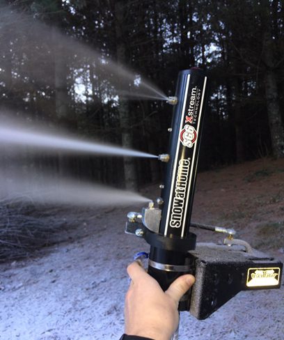
Figure 1.View of the SG6 snowmaking head in action. The majority of the water flow is expelled from the two higher nozzles, which are called “bulk” nozzles. Water and air are mixed at the lowest nozzle. The almost instant freezing of the droplets from this nozzle provides the droplets from the other nozzles a nucleus to freeze around. This image was captured with the top nozzle partially clogged, which led to the uneven flow between the upper two nozzles.
Ski areas typically employ massive water pumps and air compressors to power their snowmaking systems. Home snowmakers typically replace these large pieces of equipment with smaller versions, typically pressure washers for water pumps, and medium to large oil lubricated air compressors. The actual snowmaker is sometimes constructed from car wash nozzles and piping components. A spray of tiny water droplets is produced by the high-pressure water coming from the car wash nozzles. To create quick-freezing nuclei for the water from the top bulk nozzles to freeze around, compressed air is combined with a smaller stream of water, either internally or externally.
3 different snow machines from SnowAtHome are offered, each with a different output capacity that ranges from 1.3 gallons per minute (gpm) to 8 gpm (for comparison, the SMI super wizard, common at many ski areas, has a maximum output of 150 gpm). The SG6 snowmaker is the one utilized in the system described in this study. Two higher “bulk” nozzles and a single nucleator nozzle make up the SG6, as seen in Figure 1. It can move between 1.3 and 4.0 gpm of water. It needs an air compressor that can pump out at least 5.5 cubic feet per minute (cfm) at 90 pounds per square inch (psi). This system uses an AR Blue Clean 1600 psi pressure washer pump with a 1.6 gpm output. With an output of 5.5 cfm at 90 psi, the air compressor is a Campbell Hausfield Extreme Duty air compressor.
Since the nucleator nozzle is an external mix nozzle, the external mixing of the air and water that results in the rapidly freezing atomized droplets is achievable. Internal mixing frequently results in inconsistent air/water mix ratios that need to be regularly adjusted in order to maintain a proper balance. External mixing, on the other hand, provides a number of advantages over internal mixing. The size of the nozzles determines the air/water ratio in external mixing, which then stays constant. Furthermore, with internal mixing, the air compressor may flood with water from the pump if it shuts off for any reason, frequently resulting in irreparable damage. By maintaining a straight separation between the routes of the air and the water, external mixing prevents this.
A head constructed of extruded aluminium with radiating fins on the rear is yet another feature of the SG6 snowmaker. The solid aluminium acts as a heat sink; as a result, the temperature of the water coming from the spigot is somewhat cooled by the surrounding atmosphere. Additionally, the solid metal acts as a heat source for the snow gun head, preventing ice from forming on it. With handmade snow cannons, ice buildup is a frequent issue that frequently demands the user de-icing the nozzle head every few hours. This problem is virtually eliminated by the aluminium head, which raises the SG6’s potential for autonomy.
Several changes were made to the system itself to improve its dependability and independence potential. To begin, a water filter was connected to the pump’s input. This was done to safeguard the pump as well as the snowmaker, which has clogging-prone nozzles. Second, the air and water hoses were extended from 10 feet to 100 feet so that they could readily reach the snowmaking area from the garage where the equipment is located. The hose extension was definitely essential for automation, which is far less problematic if all of the equipment under the system’s control is in one location rather than scattered across the yard.
However, there is one significant disadvantage to extending the air and water hoses. The air hose, despite common belief, is the most likely to freeze during operation. When air is compressed, moisture in it condenses. Because the air hasn’t had time to cool down after its initial compression, condensation is typically not an issue when the air line is short. When the pipe is stretched, however, the air cools and the condensed liquid within freezes. Ice forms in the hose over time and, after a few hours, fully seals it off. The consequent shortage of air is harmful to the snow maker’s operation, which requires compressed air for optimal nucleation.
So,It is normally important to give a source of heat to the air hose if it is to be stretched. One method is to wrap a heated wire around the exterior of the hose. This approach works well for keeping ice out of the hose, but it requires more energy and can be difficult to maintain. Another very simple approach is to just connect the air and water hoses within a sleeve of pipe insulation. The heat from the domestic water supply keeps the air hose from freezing. It is also lot easier to handle with one main pipe rather than two while setting up or moving the snowmaker. A picture of the hoses connected together in this manner is shown in Figure 2.
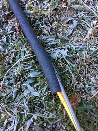
Figure 2. The air and water hoses are wrapped in an insulating sleeve so that the heat from the water prevents the air hose from freezing.
Automation System Layout and Hardware Description
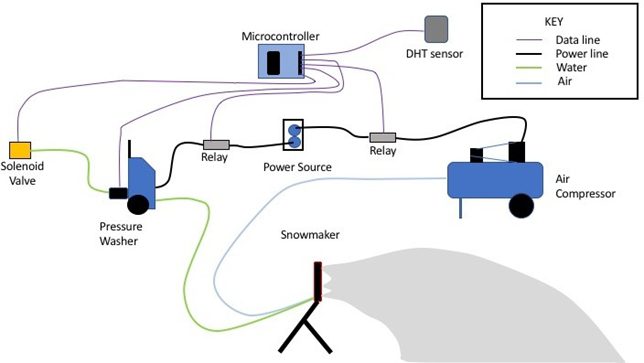
Figure 3. All of the components of the automated snowmaking system are represented in a schematic diagram. The power sources for the air compressor and pressure washer are both controlled by solid state relays. A solenoid valve controls the water supply. A DHT temperature and humidity sensor is used to read temperature and humidity digitally. Before entering the pressure washer, the water flow is calculated using an Adafruit flow sensor. An Atmega328p microcontroller is used to implement the control sequence.
Figure 2 is a schematic diagram of the full snowmaking system, including the automation components. The complete control sequence is built on an Arduino Uno microcontroller board, which has an AVR Atmega328p microprocessor. The microcontroller connects with a DHT22 humidity and temperature sensor, which delivers a readout every 2 seconds to assess if the circumstances are suitable for snowmaking.
An Adafruit flow sensor is used to measure the water flow, sending a pulse to the microcontroller for every 2 mL of fluid that passes through. Monitoring the water flow is crucial for the pump’s safety; if the water stops flowing for any reason, the pump will burn out if left running. The water flow is regulated by a solenoid valve, which the microcontroller may switch on and off. The microcontrollers use solid-state relays to operate the air compressor and pressure washer. A master power switch turns the machine on or off (in standby mode).
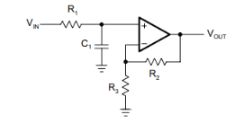
We normally use OP AMPS for noise filter on analog sensors. Here is a free e-book by MIT covering this topic op amps for everyone. Most common is First-Order Noninverting Low-Pass Filter
Here you can find high grade Instrumentational OP Amps list.
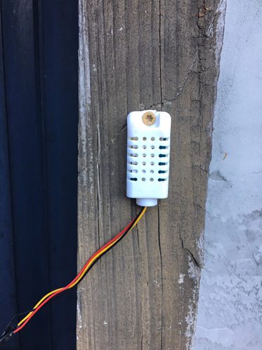
Figure 4. The DHT22 temperature and humidity sensor, is shown mounted on a wooden post outside of the control room. The DHT22 temperature and humidity sensor, shown in Figure 4, is a digital sensor with its own microcontroller. It was selected because to its inexpensive cost and relative accuracy. Temperature measurements in degrees Celsius are accurate to within 0.5 degrees Celsius. Its relative humidity values are accurate to 4% relative humidity, which is suitable for our job. Reading the DHT sensor necessitates a precisely scheduled procedure that entails delivering a series of start pulses and then reading the return 40-bit signal, which comprises the temperature, humidity, and a parity byte. Appendix A contains a detailed explanation of the DHT.h library used in this project to connect with the DHT sensor.
The Adafruit flow sensor is used in this project to ensure that water is always flowing to the pump. A revolving wheel in the sensor is rotated by flowing liquids. Every time the wheel revolves, a pulse is supplied across its data line, which the microcontroller may process. The flow rate through the sensor may be calculated by counting the number of pulses during a specific time period. The manufacturer claims that the sensor has an accuracy range of 10%. However, because the system just needs to know if water is flowing or not, the Adafruit sensor’s precision, although not perfect for more delicate applications, is more than acceptable. Appendix B contains complete documentation for the flow sensor.h file created for this project.
A solenoid valve regulates the flow of water. To operate, the solenoid valve requires 12 Volts DC. Because the microcontroller can only produce 5 volts DC, extra circuitry is required to allow the valve to be controlled by the microcontroller pin. To protect the microcontroller from the back EMF created when the solenoid valve is turned off, a transistor and a kickback diode are used. Appendix C has a complete description of the circuit. Likewise, an extra power source is required to run the air compressor and pressure washer. The microcontroller controls these 120V devices through two solid-state relays.
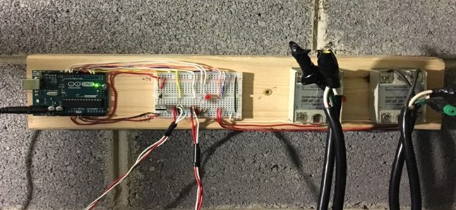
Figure 5. A picture of the wiring that has been completed to allow the microcontroller to interact with the sensors and control devices. The Arduino microcontroller board is on the far left. The breadboard is immediately to the right, where connections between the microcontroller and peripheral devices are established. The solenoid valve circuit is located on the breadboard’s far left (explained in Appendix C). To the right of that are connectors for reading the DHT sensor and the flow sensor. In the centre are two indication LEDs, one for problems and the other for when the system is turned on and functioning. The connections to power the two relays are established on the breadboard’s far right.
As part of this project, all of the electrical wiring was done by hand. All of the data lines (purple in Figure 3) were wired using 20 gauge solid copper core “doorbell” wire. On a single bread board, the circuits that allowed each device to connect with the microcontroller were constructed. A single “control panel” held the bread board, microcontroller, and relays. Figure 5 depicts the full configuration. More information on the solenoid valve circuit may be found in Appendix C.
Note: Instrumentational OP Amps can be used if you want to add extra
Program Details
The Atmega328p may be programmed in a variety of languages, including Assembly, C, C++, and Arduino, each of which provides unique capabilities and degrees of capability. On the one hand, programming in Assembly enables direct control over the hardware, which typically results in very efficient applications, but also takes careful preparation and detailed understanding of the microcontroller’s design to utilise successfully. The Arduino programming language, on the other hand, requires relatively little understanding of the inner workings of the microcontroller, and complicated procedures may be accomplished in only a few lines of code thanks to its rich library support. However, Arduino applications are frequently inefficient and restricted in their capabilities.
Taking the foregoing into account, C was chosen as a good compromise between efficiency and ease of programming. The programme that implements the automation sequence on the microcontroller is written in C on a laptop, built by the AVR-GCC compiler, then uploaded using the AVRDUDE command line software using the microcontroller’s USB interface. AVR-GCC is a cross-compiler that allows the microcontroller to be written in pure C while still providing AVR features such as interrupt vectors and extra data types. The file avr/io.h contains a lengthy number of macros that may be substituted for the actual addresses of the special function registers, considerably boosting programming efficiency and code readability. The software is broken down into three files: DHT.h, flowSensor.h, and SG6auto.c.
For debugging reasons, a serial.h file is also provided. All three files, as well as the implementation of the.h files, are fully explained and illustrated in the order given above in Appendices A-D. The files, with the exception of SG6auto.c, are libraries created to facilitate the usage of a specific device in any programme. Separating them into separate files makes it easier to test each individual component and increases portability into other programmes. It also improves code readability by dividing it into different sections with specialised functions. To improve readability, comments were freely employed.
Program flow
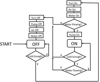
Figure above. Flow chart outlining the control sequence implemented in SG6auto.c (code included in Appendix D). Figure 3 is a flow chart that outlines the control sequence. At its core, the functioning is fairly simple: if it’s cold enough to make snow, turn the system on, if it isn’t, turn it off.
Furthermore, the programme is continually monitoring to ensure that water is flowing to the pump. If not, the system is instantly shut off. Appendix D contains the complete implementation of the control sequence in SG6auto.c. The system is turned off when it boots up. The temperature and humidity of the DHT sensor are read every minute using the DHT’s readTemp() and readHumidity() methods from DHT library.
The getWB() method is used to calculate the wet bulb temperature from the data. If the wet bulb temperature exceeds 27 degrees (the maximum reasonable temperature for snowmaking), the system remains turned off. If the wet bulb temperature is more than 28 degrees, the water is switched on. This is due to the fact that, while snowmaking is ineffective above 28 degrees, water may still freeze. As a result, water is pumped through the system to keep it from freezing. This is obviously inefficient, thus adding a heating wire to the pipes to avoid freezing when the system is turned off would be a significant improvement to system.
The turnOn() procedure is triggered if the system is turned off and the wet bulb temperature is at or below 27 degrees. First, the air and water are switched on. The flow meter is then read once every sixty seconds for sixty seconds. If water is detected, the pump is activated. If no water is detected after sixty seconds, the machine is shut down and a failed starting error is shown. The pump is around ten hose-feet away from the water source; if water isn’t flowing in sixty seconds or less, either the solenoid valve isn’t operating correctly or there is a clog in the water line (most likely ice). Either way, the system should not be turned on until the problem is fixed.
The system is in the ON state if it boots up successfully. When the programme is turned on, it checks every second to ensure that water is still flowing to the pump. If water stops flowing for whatever reason, the system is promptly turned off and a water flow interruption error is shown. The system stays in the on state if water is flowing and the wet-bulb temperature remains below 27 degrees. If the wet-bulb temperature exceeds 27 degrees, the system shuts off. The pump is shut off first, followed by the air, and then the water.
There are three error modes- ERROR1, ERROR2, and ERROR3, indicated respectively by an LED blinking once, twice, and three times in succession followed by a one second pause.
When the system enters an ERROR state, the software stays in that state until a reset is initiated outside. ERROR1 is a DHT-read error that occurs when the temperature sensor gives an incorrect reading (see Appendix A). ERROR2 indicates a failed starting, while ERROR3 indicates a water flow interruption. The same LED used to identify fault modes is turned on when the system is switched on and off when the system is shut off during normal operation.
Appendix A – Reading from the DHT22 Sensor
The DHT22 is an Adafruit digital temperature and humidity sensor. It measures temperatures to within ± 0.5 degrees Celsius and humidity to within 4% relative humidity. The DHT22 datasheet has full information. The DHT.h library implementation is provided in the source code below. The sensor adheres to a specific communication protocol. The microcontroller sends a start pulse to the sensor to start the read sequence. The sensor reacts with its own pulse, which is followed by a 40-bit signal including the temperature, humidity, and a parity byte.
The first byte of the signal indicates the humidity reading’s integer part, while the second byte is its decimal portion. Similarly, the temperature reading is made of the third and fourth bytes. The fifth byte is a parity byte, and if the reading is right, it will equal the total of the preceding four bytes. Only once per two seconds can the DHT sensor be read. An error will occur if the sensor is read before two seconds have passed since the last reading.
Appendix A – Reading from the DHT22 Sensor: Appendix A – Reading from the DHT22 Sensor
Appendix B – Reading from the Adafruit Flow Sensor
The Adafruit flow sensor is a simple gadget that can detect the rate of flow via itself with a 10% degree of accuracy. A wheel inside the sensor should revolve once for every 2.25 mL of fluid that goes through it. Each time the wheel is turned, a +5 Volt pulse goes down the data line, which the microcontroller can read. The frequency of rotation of the wheel determines the duration of the pulse.
The flowSensor.h getFlowrate() method polls the flow sensor pin at one second intervals and counts the number of pulses before converting the number of pulses per second to gallons per minute. The function then returns the outcome of the calculation.
Appendix B – Reading from the Adafruit Flow Sensor: Appendix B – Reading from the Adafruit Flow Sensor
Appendix C – Supporting Circuitry for the Solenoid Valve
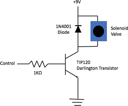
Figure C.1.The circuit that allows a microcontroller pin to switch on and off a solenoid valve. A 1KW resistor connects the microcontroller pin to the base of the NPN transistor. When the pin is turned off, a 1N4001 is utilized as a kickback diode to protect the remainder of the circuit from the back EMF created by the solenoid valve.
Figure C.1 demonstrates the circuit used to interact the microcontroller with the solenoid valve. Two constraints inspire the circuit. First, the microcontroller is incapable of supplying enough current to power the solenoid valve. As a result, the pin is linked to the base of a TIP120 Darlington transistor, which controls current from a 12 Volt DC power supply to operate the solenoid valve. Moreover, when switched off, the solenoid valve functions as a huge inductor, creating a strong back EMF that might cause considerable damage to the microcontroller’s circuitry. To counteract this, a 1N4001 kickback diode is incorporated, preventing electricity from flowing back to the microcontroller. As a result, the microcontroller may securely operate the solenoid valve.
Appendix D – Control Sequence Documentation
Appendix D – Control Sequence Documentation: Appendix D – Control Sequence Documentation
- What is the most important environmental factor for snowmaking?
Wet bulb temperature, which combines ambient temperature and humidity, is the most important factor. - How does the system ensure nucleation for snow formation?
The SG6 uses an external nucleator nozzle that mixes compressed air and water to create freezing nuclei for larger droplets. - Can the system detect if water flow stops?
Yes, an Adafruit flow sensor sends pulses to the microcontroller to detect if water is flowing and triggers shutdown if flow stops. - How does the controller decide to turn the system on?
The microcontroller reads DHT22 sensor data, calculates wet bulb temperature, and turns on the system when wet bulb is at or below 27 degrees (with water started at 28 degrees to prevent freezing). - What protections are used when driving the solenoid valve?
A TIP120 transistor drives the 12 V solenoid and a 1N4001 kickback diode protects the microcontroller from back EMF; a 1 kΩ resistor is used at the transistor base. - Why are the air and water hoses sleeved together?
Wrapping the air and water hoses in pipe insulation uses heat from the water to prevent the air hose from freezing when extended. - How are the compressor and pressure washer controlled?
The microcontroller uses solid-state relays to switch power to the air compressor and pressure washer. - What error modes exist and how are they indicated?
There are three errors: ERROR1 DHT-read error, ERROR2 failed starting, and ERROR3 water flow interruption; indicated by LED blinking patterns (one, two, or three blinks). - What programming environment is used for the controller?
The Atmega328p is programmed in C using AVR-GCC and uploaded with AVRDUDE; software is split into DHT.h, flowSensor.h, and SG6auto.c files. - Why is the SG6 head made of aluminium?
The extruded aluminium head acts as a heat sink and heat source to cool incoming water and reduce ice buildup on the head, improving autonomy.