Summary of Automated Bioactive Tropical Reptile Vivarium (using Arduino)
This article details the construction of an automated bioactive tropical vivarium for reptiles like crested geckos using Arduino. The system automates humidity, temperature monitoring, lighting, and door locking while providing a user interface via an OLED screen. It utilizes various sensors and actuators to maintain optimal habitat conditions without constant manual intervention.
Parts used in the Automated Bioactive Tropical Reptile Vivarium:
- Vivarium
- DHT22 Temperature Humidity Sensor
- Micro Servo 9g
- Ultrasonic Mist Maker
- 12V DC Fans (2x)
- DS3231 RTC Module
- 2-Channel 5v Relay Modules (2x)
- 128x64 OLED Screen
- Joystick Module
- Ultrasonic Distance Sensor
- Lighting system (hood, 5000K bulb, UVB bulb)
- Power supplies (12V, 5V, 9V DC)
- LEDs (3x) and 220 Ohm resistors (3x)
- Extension cords and Power Strip
- Water Tub
- PVC Pipe and connectors
- 3D printed parts (Fogger Float, Fusion, Connector, Relay Box components)
- Tools (Hot Glue Gun, 3D Printer, Drill, etc.)
I have multiple bioactive tropical vivariums for my crested geckos, and I always need to spray them morning and night, as well as when the humidity is too low (which happens multiple times per day), and I have to turn on and off the lights and monitor the temperature. I’ve made some small projects with my Arduinos in the past, so I thought I could create an automation system for my vivariums. I have multiple vivariums, but this tutorial will walk you through the automation of just one.

Here are the elements I’ve decided to implement:
- Temperature-humidity sensor
- Clock/timer
- Ultrasonic fogger
- Servo door lock (so that small children can’t open the doors at their leisure :))
- Water level sensor
- Lights control
- OLED Display Menu
Note: In the future, I plan to add other features such as support for multiple terrariums, an automatic mister (in addition to the fogger), and a waterfall pump, and I will either add those to this tutorial or make another one.
This vivarium can be used for many animals, not just crested geckos. Other New Caledonian geckos, dart frogs, day geckos, and some snakes could all be good options for this terrarium. However, some things, such as humidity and lighting, may need to be tweaked in the code to fit the needs of your animal.
Supplies
- Vivarium
- This tutorial doesn’t go over how to set up a vivarium, only how to automate it. Vivarium should already be set up.
- DHT22 Temperature Humidity Sensor
- A DHT11 will also work, but it will be less accurate
- Micro Servo 9g
- Ultrasonic Mist Maker
- 2x 12V DC Fans
- DS3231 RTC Module
- 2x 2-Channel 5v Relay Module
- 128×64 OLED Screen
- Joystick Module
- Ultrasonic Distance Sensor
- Lighting system:
- Light hood that fits your terrarium
- 5000K daylight bulb
- 5.0 13W UVB bulb (not necessary for crested geckos, but may be helpful)
- Power supplies:
- 12V DC Power supply
- External power supply for fans
- 5V DC Power supply
- External power supply for components
- 9V DC Power supply
- Power supply for Arduino board
- 12V DC Power supply
- 3x LEDs
- 3x 220 Ohm resistors
- 2x Generic 2-prong Extension Cord
- Power Strip
- DC Jack –> Wire adapters
- Jumper Wires
- Spritzer bottle
- Water Tub (I used a 27qt Sterilite tub from Walmart)
- Duct tape
- Foam board
- Corrugated Plastic Board
- Scrap wood or other material to make a stand for the
- 3/4″ or 1″ PVC Pipe
- About 2-3 ft of pipe
- Two 90 degree elbow connectors
- Tools:
- Hot Glue Gun
- 3D Printer
- Electric Drill
- Step drill bit or hole saw if you have one
- Drill bits
Step 1: 3D Printed Parts
Here are the stl files for 3D printing. The relay box is modular, so the boxes can slide together.
Attachments
- FoggerFloatFusion.stlDownloadView in 3D
- FogBinConnector.stlDownloadView in 3D
- RelayBoxBase.stlDownloadView in 3D
- RelayBoxLid.stlDownloadView in 3D
- RelayBoxHoleCover.stlDownload
Step 2: Setting Up the Bin
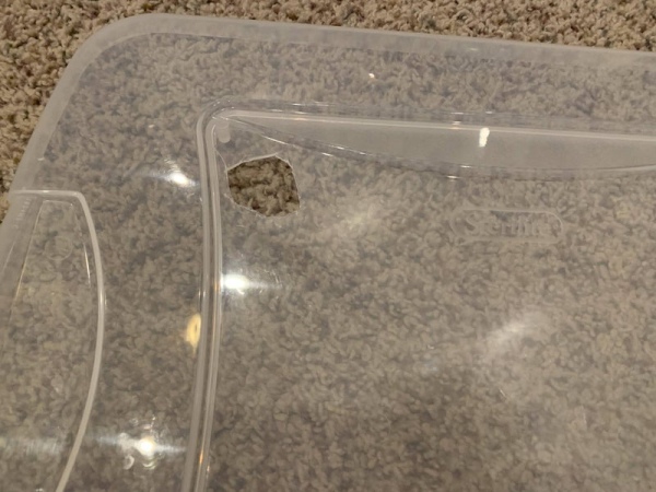
First, cut a hole in the lid of the bin for an exit for the fog. This should be large enough for the PVC pipe to be able to go through and fit snugly or tightly. If you have a step drill bit or a hole saw, that would work great. I don’t have one of those, so I just used a utility knife and even though the holes aren’t perfect, they work.
Next, drill a bunch of holes in a circle as shown in the pictures. The circle should be about as big as the 12V fan you’re using. This will be where the fan blows in air to push the fog out the PVC pipe.
Then, drill or cut a hole that is large enough for the rubber piece on the fogger to fit through and seal.
These holes can be wherever on the lid you want them to be. I just put them in a line near the side for convenience. For best air flow, the fan and pipe holes should be on opposite sides of the lid.
Cut another hole about the size of the ultrasonic distance sensor module wherever you want the water level sensor tube to be.
Cut the corrugated plastic sheet into a rectangle that is about 16″ long and a height of a little bit less than the height of the bin. Then, cut through one layer of the board every 4″ so that the board can fold into a rectangular prism that is about 4 inches square and a bit less then the height of the bin. This is the “tube.” Use hot glue to glue the rectangle into place and fill the corners so that air can’t enter the tube. Glue the tube onto the lid so that it goes around the hole for the sensor. This will prevent the fog from affecting the accuracy of the ultrasonic sensor.
Push the 3D printed pipe-to-bin connector through the big hole. Then, push the 90° elbow connector onto the printed connector. Connect the rest of the PVC pipe to that connector in order to bring the fog into the terrarium however you want it.
Step 3: Installing Components
Feed the DC power jack from the fogger module through the medium-sized hole and fit the rubber piece into the hole so it is snug. Then, plug the jack into the other end that connects to the DC adapter that came with the fogger.
Print the fogger floater and put the fogger into the bottom of the floater. This floater will keep the fogger the correct distance away from the surface while still creating enough fog. I secured mine with rubber bands, but you don’t have to do that, it should stay in just fine.
Most reptile terrariums have optional holes at the back of the lid for feeding cables through; open one hole and feed the DHT22 wires through so that the sensor is on the inside of the vivarium.
Put the lighting fixture on top of the terrarium where you want it.
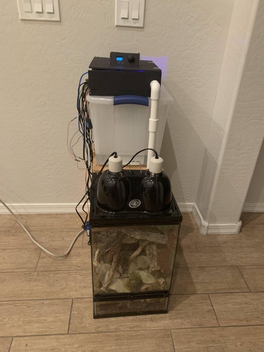
Fill the bin about 3/4 full of water and put it on top of your bin stand. Put the terrarium in front of the stand and position the fog pipe so that it enters the terrarium where you want it to.
Use hot glue, silicone, etc. to connect the servo onto the side of the terrarium so the horn sticks out in front of the door when the servo is set to “closed.”
Step 4: Wiring
I used a breadboard for most of the wiring, but for a more permanent option you can solder the wires together. I soldered 220 ohm resistors to the LEDs.
For the Arduino power supply module, I used a DC jack to +/- wire adapter to add a switch. This isn’t necessary if you don’t want to go into the trouble for the Arduino power, but it is necessary for the 5v power supply, which is plugged straight into the breadboard, and the 12v power supply, which is plugged straight into the relay module for the fans.
Print two relay boxes. Put one relay module in each box. Cut and strip the hot wire (the one connected to the small prong) on each extension cord and screw the ends into the common terminal and the NO (normally open) terminal in each relay of one of the modules. For the other module, connect the positive end of the 12v power supply into both of the common terminals in the module and connect the positive end of each fan into one of the NO terminals. Connect the ground of the fans to the ground on the 12v power supply. Cover the big holes on top of the boxes with the relay box hole cover.
Arduino:
- Pin 2 – fogger fan relay pin
- Pin 3 – dehumidifying fan relay pin
- Pin 4 – lights relay pin
- Pin 5 – button pin on joystick
- Pin 6 – water refill LED (red)
- Pin 7 – fogger relay pin
- Pin 8 – fogger on LED (blue)
- Pin 9 – temp irregularity LED (red)
- Pin 10 – lock servo signal pin
- Pin 11 – ultrasonic sensor echo pin
- Pin 12 – ultrasonic sensor trig pin
- Pin 13 – DHT22 signal pin
- A0 – Joystick x-output
- A1 – Joystick y-output
- SCL – SCL on OLED screen and RTC
- SDA – SDA on OLED screen and RTC
Make sure to connect the Arduino ground to the ground on the breadboard/5v power supply.
Finally, plug the fogger into the extension cord connected to the relay that corresponds to pin 2 on the Arduino, and plug in the lights into the cord that corresponds to pin 4 on the Arduino. Connect the + and – pins from the servo into the 5v power supply on the breadboard.
Plug all of the extension cords and power supplies into a power strip.
Step 5: Foam Board Covering
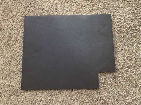
This covering could change, depending on your wiring configuration and the components you decide to implement.
Using the foam board:
- Cut a rectangle that’s about 10″x12″ and cut a hole that’s about 2″x2″ in the corner for the PVC pipe.
- Cut strips that are about 0.6″ wide and about as long as the sides. The longest strip should be a bit shorter than the actual side in order to accommodate the wires for the fogger, fan, and distance sensor. Use hot glue to stick them on the bottom to elevate the platform and give some clearance for the fan and sensor.
- Cut strips that are about 2″ wide and the same length as the last ones, except for the long side. Make this one about 4″ long so that the extension cords for the relays and the power cords can come out. Cut a hole in the one of the sides so that the pipe can come out. Glue these sides on.
- Cut another rectangle that is 10″x12″. Cut a smaller rectangle somewhere in the middle of it that is 4″x2″. Cut holes for the LEDs, OLED screen, and joystick. Glue the components on with hot glue.
- For ease of access, use tape to connect one side of the lid to the rest of the foam board.
Step 6: Code
Upload the Vivarium_Controller_setup and the Vivarium_Controller_functions files into the Arduino IDE. You may have to copy and paste one of them into the other because I set up the code as two different tabs in the Arduino IDE. The “setup” one has all the variables and bitmaps, and the “functions” one has all of the functions and loops.
All of these libraries should be available in the “Manage Libraries” section in the Arduino IDE.
Libraries to install:
- RTClib
- Adafruit_GFX
- Adafruit_SSD1306
- Servo (by Arduino)
- DHT-sensor-library (by adafruit)
- I used a different library, so if you use this one you may have to tweak the code, but I included the “.h” and “.cpp” files for the library I’m using, so feel free to use those as well.
Step 7: Done!
Congratulations! You now have a working tropical vivarium for your reptile!
Source: Automated Bioactive Tropical Reptile Vivarium (using Arduino)
- What animals can this vivarium be used for?
This vivarium is suitable for many animals including New Caledonian geckos, dart frogs, day geckos, and some snakes, though code tweaks may be needed. - Can I use a DHT11 sensor instead of the DHT22?
Yes, a DHT11 will work but it will be less accurate than the DHT22. - How do I ensure the ultrasonic sensor accuracy is not affected by fog?
You must build a tube from corrugated plastic around the water level sensor hole to prevent fog from affecting its readings. - Does the UVB bulb need to be included for crested geckos?
No, the UVB bulb is not necessary for crested geckos, though it may be helpful for other species. - What libraries are required to run the Arduino code?
The required libraries include RTClib, Adafruit_GFX, Adafruit_SSD1306, Servo, and DHT-sensor-library. - How should the fan and pipe holes be positioned on the bin lid?
For best airflow, the fan and pipe holes should be placed on opposite sides of the lid. - Can I solder the wires together instead of using a breadboard?
Yes, you can solder the wires together for a more permanent option, though a breadboard was used in this tutorial. - What is the purpose of the servo door lock?
The servo door lock prevents small children from opening the terrarium doors at their leisure.