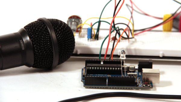
Summary of Audio Input using an Arduino Board
This article guides users on interfacing audio input with an Arduino to create sound-responsive projects like beat detectors, VU meters, and digital effects. It details the process of amplifying and offsetting audio signals from a microphone to fit the Arduino's 0-5V analog input range using an op-amp circuit powered by dual 9V batteries. The guide covers signal preparation, jack wiring, and component selection for building a functional audio sampling system.
Parts used in the Audio Input Project:
- Microphone Radioshack 33-3038
- TL072 or TL082 Op-Amp IC
- Two 9V batteries
- Two 9V battery snap connectors
- Mono audio jack (1/4" or 1/8")
- LED
- 10kOhm linear potentiometer
- Three 100kOhm 1/4watt resistors
- 10uF electrolytic capacitor
- 47nF ceramic capacitor
- Arduino Uno board
- 22 gauge wire
- Solder
Send sound into your Arduino. This Instructable will show you how to prepare audio so that it can be sampled and processed by an Arduino to make sound responsive projects and audio effects. (This article is a companion to another Instructable I’ve written about building an audio output circuit for an Arduino, find that here)
Some ideas that come to mind include:
beat detection– trigger lighting effects, build a set of turntables that beat match themselves, or make a robot that dances along with the music you play for it
amplitude detection– make a simple vu meter with LEDS
frequency analysis– you could make a project that reacts to different frequencies in different ways, recognizes certain melodies, turns audio into MIDI data, or translates incoming frequencies into square waves with the tone() library
digital effects boxes/digital signal processing– check out what I did with my vocal effects box (all processing done with Arduino), lots of possibilities here: pitch bending, distortion, sampling, delay,reverb, granular synthesis, mixing, and much more… I’ve provided code in this Instructable that lets you sample at up to 38.5kHz. Here is another instructable describing how to set up a simple audio out circuit with Arduino.
digital recorder– with the addition of an SD card of course (the Arduino has very limited memory by itself), this opens up the possibility of looping large samples and doing lots of other digital manipulations to pieces of stored audio The circuits and code provided here are compatible with SD card shields that communicate via SPI.
graphical representations of sound– Arduino oscilloscope/visualizer
Feel free to use any of the info in this Instructable to put together an amazing project for the DIY Audio Contest! We’re giving away an HDTV, some DSLR cameras, and tons of other great stuff! The contest closes Nov 26.
Parts list:
(x1) Microphone Radioshack 33-3038
(x1) TL072 Digikey 296-14997-5-ND or TL082 Digikey 296-1780-5-ND (TL081/TL071 are fine too) I used a tl082 in my examples
(x2) 9V battery
(x2) 9V battery snap connector Radioshack 270-324
(x1) mono audio jack 1/4″ Radioshack 274-340 or Radioshack 274-252 or 1/8″ Radioshack 274-333or Radioshack 274-251
(x1) LED Digikey C513A-WSN-CV0Y0151-ND
(x1) 10kOhm potentiometer linear Digikey 987-1301-ND
(x3) 100kOhm 1/4watt resistors Digikey CF14JT100KCT-ND
(x1) 10uF electrolytic capacitor Digikey P5134-ND
(x1) 47nF ceramic capacitor Digikey P4307-ND
(x1) Arduino Uno (Duemilanove is fine too) Sparkfun DEV-09950
Additional Materials:
22 gauge wire
solder
Step 1: Preparing audio signals for Arduino
If you’ve ever recorded audio on your computer, you may have seen it represented as a waveform like the one in fig 1. If you zoom in on this wave (as in fig 2) you will see that the shape is made of thousands of tiny oscillations back and forth. This is called an audio signal and when we are dealing with audio signals in electronics, these oscillations represent oscillating voltages over time.
When we look at an audio signal with an oscilloscope, we see a similar picture (fig 3). Notice how the audio signal in fig 3 oscillates around a center voltage of 0V; this is typical of audio signals. Theamplitude of an audio signal is the distance between its center voltage and its high or low peak. The amplitude of the wave in fig 3 is 2V: it reaches a maximum voltage of +2V and a minimum voltage of -2V. This is a problem if we want to measure the audio signal with one of the Arduino’s analog inputs because the Arduino can only measure voltages between 0 and 5V. If we tried to measure the negative voltages in the signal from fig 3, the Arduino would read only 0V and we would end upclipping the bottom of the signal. In this Instructable I’ll show you how you can amplify and offset audio signals so that they fall within this 0-5V range. Ideally you want a signal with an amplitude of 2.5V that oscillates around 2.5V (like in fig 7) so that its min voltage is 0V and its max voltage is 5V (see the calculations below).
Min voltage = Center Voltage – Amplitude
Min voltage = 2.5V – 2.5V = 0V
Max Voltage = Center Voltage + Amplitude
Max Voltage = 2.5V + 2.5V = 5V
Fig 4 shows the signal coming straight out of the microphone on an oscilloscope. The signal is relatively weak, with an amplitude of only 200mV, you may find that signals from other sources (ipods, guitars, record players…) also produce audio signals with small amplitudes. These signals need to be amplified to get them up to the amplitude we want (2.5V). Amplification means increasing the amplitude (distance between the center point and max or min) of a signal. Amplification also buffers the audio source (in my case this was a microphone) from any loads that you may put on it later in the circuit, which is a good thing because it prevents distortion.
Fig 5 shows the same microphone signal after amplification, you can see how the height of the peaks has increased so that the wave has an amplitude of 2.5V. But since the center voltage of the wave is still 0, the wave is oscillating between -2.5 and +2.5V. It will need to be DC offset to correct this. DC offset means changing the center voltage that the wave oscillates around (the average voltage of the wave). Fig 6 shows the signal after it has been DC offset; it still has an amplitude of 2.5V, but the center voltage is 2.5V instead of 0V, so the wave never drops down below 0V. (Note- the slight change in shape between the signals in figures 5 and 6 is dues to changes in my voice between the two pics, it has nothing to do with the circuit). The signal in fig 6 is ready to go to an Arduino analog input pin.
Step 2: Prepare audio jack
In this Instructable, I’m only going to talk about how to route one channel of audio into an Arduino. It is possible to copy the same circuit I’ve proposed here many times to add multiple channels, but it can complicate/slow things down in the code and at some point you will probably have to lower your sampling rate. I’ll leave it up to you to figure out the details, but please post what you learn in the comments! Almost all microphones and electronic instruments are mono, meaning they only have one microphone element or pickup which is generating a signal (as opposed to stereo). You can tell for sure by looking at the plug and comparing it to the image above. My microphone has a 1/4″ plug on it so I used a 1/4″ jack for this instructable, you may find that you need a 1/8″ jack, but the main ideas here still apply.
Solder a black wire to the ground pin of the mono jack. The ground pin is usually the larger pin on the jack, test for continuity with the threaded portion of the jack to make sure that you have located the ground pin correctly (see fig 3). Solder a green wire to the signal pin of the mono jack. Test for continuity with the clip that extends out from the jack (fig 3).
If you have an oscilloscope handy, connect the reference to the black wire, connect the probe tip to the green wire, plug the microphone in the jack and look for a signal (fig 5). The signal from my microphone has an amplitude of about 200mV.
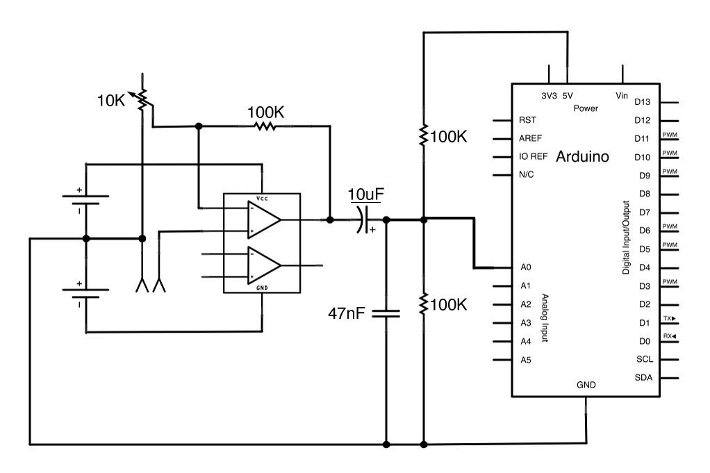
Step 3: Non-Inverting Amplifier
The amplifier is the first step in the circuit, it increases the amplitude of the signal from around + or – 200mV to + or – 2.5V (ideally). The other function of the amplifier is to protect the audio source (the thing generating the audio signal in the first place) from the rest of the circuit. The outgoing amplified signal will source all its current from the amplifier, so any load put on it later in the circuit will not be “felt” by the audio source (the microphone element in my case). Do this by setting up one of the op amps in the TL072 or TL082 package in a non-inverting amplifier configuration.
The datasheet of the TL072 or TL082 says that it should be powered with +15 and -15V, but since the signal will never be amplified above + or – 2.5V it’s fine to run the op amp with something lower. I used two nine volt batteries wired in series to create a + or – 9V power supply.
(x1) Microphone Radioshack 33-3038
(x1) TL072 Digikey 296-14997-5-ND or TL082 Digikey 296-1780-5-ND (TL081/TL071 are fine too) I used a tl082 in my examples
(x2) 9V battery
(x2) 9V battery snap connector Radioshack 270-324
(x1) mono audio jack 1/4″ Radioshack 274-340 or Radioshack 274-252 or 1/8″ Radioshack 274-333or Radioshack 274-251
(x1) LED Digikey C513A-WSN-CV0Y0151-ND
(x1) 10kOhm potentiometer linear Digikey 987-1301-ND
(x3) 100kOhm 1/4watt resistors Digikey CF14JT100KCT-ND
(x1) 10uF electrolytic capacitor Digikey P5134-ND
(x1) 47nF ceramic capacitor Digikey P4307-ND
(x1) Arduino Uno (Duemilanove is fine too) Sparkfun DEV-09950
For more detail: Audio Input using an Arduino Board
- How can I prepare audio signals for the Arduino?
You must amplify and DC offset the signal so it oscillates between 0V and 5V instead of negative voltages. - Can I use this circuit for stereo audio?
The article focuses on routing one channel; adding multiple channels may complicate the code and require lowering the sampling rate. - What power supply does the op-amp need?
The TL072 or TL082 was powered by two 9V batteries wired in series to create a + or - 9V supply. - Does the amplifier buffer the audio source?
Yes, the non-inverting amplifier configuration protects the audio source from loads placed later in the circuit. - What is the ideal amplitude for the Arduino input?
An amplitude of 2.5V oscillating around a center voltage of 2.5V ensures the signal stays within the 0-5V range. - Can I record audio with this setup?
Yes, by adding an SD card shield that communicates via SPI, you can loop large samples and store audio. - What sampling rate does the provided code support?
The code allows sampling at up to 38.5kHz. - Which components are compatible with the Arduino Duemilanove?
The circuits and code are compatible with both the Arduino Uno and the Duemilanove.