Summary of ATtiny85 – Spectrum Analyzer on RGB Led Matrix 16×20
This article details building a music spectrum analyzer using a DigiSpark ATtiny85 to drive a 16x20 RGB LED matrix. The system processes audio signals via FFT and displays the spectrum using Bit Angle Modulation for color variation. The project involves soldering LEDs onto a PCB, connecting shift registers and transistors for row/column scanning, and programming the microcontroller with specific libraries to handle real-time audio visualization on a tea table or desk.
Parts used in the Music Spectrum Analyzer:
- 1 x DigiSpark ATtiny85
- 320 x Common Anode RGB LEDs
- 16 x A1013 Transistors
- 2 x Shift Register 74HC595N
- 9 x Power Logic 8-Bit Shift Register TPIC6B595N
- 12 x 0.1uF Decoupling Capacitors
- 100 x 100Ω Resistors
- 16 x 1kΩ Resistors
- 4 x 10kΩ Resistors
- 1 x Single-Side Copper Prototype PCB Size A4
- 2 x Clear Acrylic Plate Size A4
- 2 x Male & Female 40pin 2.54mm Header
- 1 x Power Supply Adapter 5V/2A
- 1 x DC Power Supply Female Socket
- 1 x DC Power Supply Screw Type
- 8 x Copper Standoff Spacers 20mm
- 1 x 3.5mm Audio Jack
- 2 meter x Rainbow Color Flat Ribbon Cable
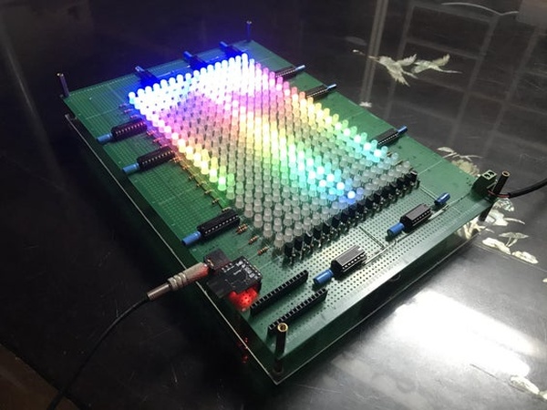
Continuing with ATtiny85, today I’d like to share how to build a music spectrum analyzer on 16×20 RGB led matrix. The music signal FFT transformation and LED Bit Angle Modulation are all carried out by one DigiSpark ATtiny85.
Please watch my video below:
Step 1: Things We Need
Main components are as follows:
- 1 x DigiSpark ATtiny85.
- 320 x Common Anode RGB LEDs.
- 16 x A1013 Transistors.
- 2 x Shift Register 74HC595N.
- 9 x Power Logic 8-Bit Shift Register TPIC6B595N.
- 12 x 0.1uF Decoupling Capacitors.
- 100 x 100Ω Resistors.
- 16 x 1kΩ Resistors.
- 4 x 10kΩ Resistors.
- 1 x Single-Side Copper Prototype PCB Size A4.
- 2 x Clear Acrylic Plate Size A4.
- 2 x Male & Female 40pin 2.54mm Header.
- 1 x Power Supply Adapter 5V/2A.
- 1 x DC Power Supply Female Socket.
- 1 x DC Power Supply Screw Type.
- 8 x Copper Standoff Spacers 20mm.
- 1 x 3.5mm Audio Jack.
- 2 meter x Rainbow Color Flat Ribbon Cable.
Step 2: Schematic
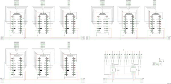
You can download the project schematic in PDF format HERE.
The components for controlling a RGB led matrix 16×20:
- Columns (cathodes) scanning: including 3 groups of TPIC6B595N to control 20 columns, each group includes 3 x TPIC6B595N for 3 colors (Red, Green & Blue), for example with blue color:
- Rows (anodes) scanning: including 2 x 74HC595N and 16 x A1013 transistor to control 16 rows.
Step 3: Soldering and Arrangement
Firstly, I soldered 320 RGB leds on the PCB, from outer edge of the PCB I left about 15~16 holes to reserve space for control components.
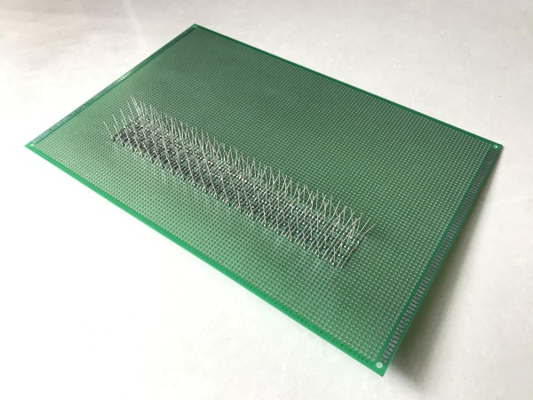
As picture above, I soldered all cathode pins in same column (total 20 columns – cathode with R, G, B pin) together after aligning leds on the top side.
After soldering 20 led columns, I soldered anode led pins in same row ( total 16 rows – anode) together by bending anode led pins so that there is a gap between the rows and columns, avoiding them touching each other.
The 16×20 RGB led matrix has been done!
Then around this led matrix, I soldered all row (2 x 74HC595N + 16 x A1013) and column (9 x TPIC6B595N) scanning components, female header for ATtiny85, 3.5mm audio jack and power supply socket.
I didn’t use wires in this project but instead I used the led pins which were left from many led related projects.
I want all components and connections to be seen, so I covered the top and botom of PCB by clear arcylic plates.
Done!!! And I can put it on my tea table for decoration.
If you have a PCB project, please visit the NEXTPCB website to get exciting discounts and coupons.
- Only $0 for 1-4 layer PCB Prototype: https://www.nextpcb.com/pcb-quote?act=2&code=tunen…
- New customer get $100 coupons, register at: https://www.nextpcb.com/register?code=tunendd
Step 4: Programing and How It Works
The project code is as below:
/*
Tested with Arduino 1.8.13, the ATTinyCore and libraries:

  https://github.com/SpenceKonde/ATTinyCore
  https://github.com/JChristensen/tinySPI
  https://github.com/kosme/fix_fft

Connections:
  - DigiSpark ATtiny85 P0 (PB0) - BLANK PIN OF 74HC595 & TPIC6B595.
  - DigiSpark ATtiny85 P1 (PB1) - DATA PIN OF TPIC6B595
  - DigiSpark ATtiny85 P2 (PB2) - CLOCK PIN OF 74HC595 & TPIC6B595.
  - DigiSpark ATtiny85 P3 (PB3) - LATCH PIN OF TPIC6B595 & 74HC595
  - DigiSpark ATtiny85 P4 (PB4) - AUDIO PIN.
*/
#include <tinySPI.h>            // https://github.com/JChristensen/tinySPI
#include "fix_fft.h"            // https://github.com/kosme/fix_fft
#define HARDWARE_SPI        1   // Set to 1 to use hardware SPI, set to 0 to use software SPI
#define BAM_RESOLUTION      2   // Define Bit Angle Modulation BAM resolution,

// Digispark Attiny85 pin definitions
const int
    DATA_PIN(1),                // Serial data in (Data pin)
    CLOCK_PIN(2),               // Shift register clock (Clock pin)
    LATCH_PIN(3),               // Storage register clock (Latch pin)
    BLANK_PIN(0);               // Output enable pin (Blank pin)
    //AUDIO_PIN(4);             // Input audio pin (Audio pin)

//**************************************************BAM Variables**********************************************************//

byte red[BAM_RESOLUTION][48];
byte green[BAM_RESOLUTION][48];
byte blue[BAM_RESOLUTION][48];

// Anode low and high byte for shifting out.
byte anode[16][2]= {{B11111110, B11111111}, {B11111101, B11111111}, {B11111011, B11111111}, {B11110111, B11111111}, {B11101111, B11111111}, {B11011111, B11111111}, {B10111111, B11111111}, {B01111111, B11111111},
                    {B11111111, B11111110}, {B11111111, B11111101}, {B11111111, B11111011}, {B11111111, B11110111}, {B11111111, B11101111}, {B11111111, B11011111}, {B11111111, B10111111}, {B11111111, B01111111}};

int row;
int level;
int BAM_Bit, BAM_Counter=0;

// Colorwheel array for spectrum analyzer
byte colorwheels[20][3]={{0, 0, 3},
                              {0, 0, 3},
                              {1, 0, 3},
                              {2, 0, 3},
                              {3, 0, 3},
                              {3, 0, 2},
                              {3, 0, 1},
                              {3, 0, 0},
                              {3, 1, 0},
                              {3, 2, 0},
                              {3, 3, 0},
                              {2, 3, 0},
                              {1, 3, 0},
                              {0, 3, 0},
                              {0, 3, 1},
                              {0, 3, 2},
                              {0, 3, 3},
                              {0, 2, 3},
                              {0, 1, 3},
                              {0, 0, 3}};

//****************************************************Fix_FFT Variables********************************************************//

int8_t data[32];
unsigned long useconds;
int sum_data;

//************************************************************************************************************//

void setup()
{
  row = 0;
  level = 0;
  #if HARDWARE_SPI == 1
    SPI.begin();                   // Start hardware SPI.
  #else
    pinMode(CLOCK_PIN, OUTPUT);    // Set up the pins for software SPI
    pinMode(DATA_PIN, OUTPUT);
  #endif
  // Set up the pins for software SPI
  pinMode(LATCH_PIN, OUTPUT);
  digitalWrite(LATCH_PIN, HIGH);
  noInterrupts();
  // Clear registers
  TCNT1 = 0;
  TCCR1 = 0;
  // Reset to $00 in the CPU clock cycle after a compare match with OCR1C register value
  // 50 x 3.636 = 181.8us
  // If software SPI is used, this value should be increased.
  OCR1C = 50;
  // A compare match does only occur if Timer/Counter1 counts to the OCR1A value
  OCR1A = OCR1C;
  // Clear Timer/Counter on Compare Match A
  TCCR1 |= (1 << CTC1);
  // Prescaler 64 - 16.5MHz/64 = 275Kz or 3,636us
  TCCR1 |= (1 << CS12) | (1 << CS11) | (1 << CS10);
  // Output Compare Match A Interrupt Enable
  TIMSK |= (1 << OCIE1A);
  interrupts();
  clearfast();

  // ADC Control and Status Register
  ADCSRA &= ~((1 << ADPS0) | (1 << ADPS1) | (1 << ADPS2));
  ADCSRA |= ((1 << ADPS2) |(1 << ADPS0));
}

void loop()
{
  sum_data = 0;
  for (int i = 0; i < 32; i++)
  {
    useconds = micros();
    data[i] = ((analogRead(A2)) >> 2) - 128;    // DigiSpark ATtiny85 analog pin A2 at PB4
    sum_data += data[i];
    while (micros() < (useconds + 100))
    {
    }
  }
  for (int i = 0; i < 32; i++)
  {
    data[i] -= sum_data/32;
  }

  fix_fftr(data, 5, 0);

  for(int j = 0; j < 16; j++)
  {
  data[j] = 4*((float)data[2*j]+ (float)data[2*j+1]);   // Everage & scale 2 bars together to get 16 bars
  }

for (byte xx=0; xx<20; xx++)
  {
  for (byte yy=0; yy < 16; yy++)
  {
        if (xx > data[yy])
        {
          LED(19-xx, yy, 0, 0, 0);
        }
        else
        {
          LED(19-xx, yy, colorwheels[xx][0], colorwheels[xx][1], colorwheels[xx][2]); // Colorwheel spectrum bars
        }
      }
  }

}
void LED(int X, int Y, int R, int G, int B)
{
  X = constrain(X, 0, 19);
  Y = constrain(Y, 0, 15);

  R = constrain(R, 0, 3);
  G = constrain(G, 0, 3);
  B = constrain(B, 0, 3);

  int WhichByte = int(Y*3+ X/8);
  int WhichBit = (X%8);

  for (byte BAM = 0; BAM < BAM_RESOLUTION; BAM++)
  {
    bitWrite(green[BAM][WhichByte], WhichBit, bitRead(G, BAM));
    bitWrite(red[BAM][WhichByte], WhichBit, bitRead(R, BAM));
    bitWrite(blue[BAM][WhichByte], WhichBit, bitRead(B, BAM));
  }
}

void clearfast ()
{
  memset(green, 0, sizeof(green[0][0]) * BAM_RESOLUTION * 48);
  memset(red, 0, sizeof(red[0][0]) * BAM_RESOLUTION * 48);
  memset(blue, 0, sizeof(blue[0][0]) * BAM_RESOLUTION * 48);

}

ISR(TIMER1_COMPA_vect){

PORTB |= ((1<<BLANK_PIN));      // Set BLANK PIN low - 74HC595 & TPIC6B595

if(BAM_Counter==8)
BAM_Bit++;

BAM_Counter++;

// Anode scanning
DIY_SPI(anode[row][1]);       // Send out the anode level high byte
DIY_SPI(anode[row][0]);       // Send out the anode level low byte

switch (BAM_Bit)
{
  case 0:
    DIY_SPI(green [0][level + 2]);  DIY_SPI(green [0][level + 1]);  DIY_SPI(green [0][level + 0]);
    DIY_SPI(red   [0][level + 2]);  DIY_SPI(red   [0][level + 1]);  DIY_SPI(red   [0][level + 0]);
    DIY_SPI(blue  [0][level + 2]);  DIY_SPI(blue  [0][level + 1]);  DIY_SPI(blue  [0][level + 0]);

    break;
    case 1:
    DIY_SPI(green [1][level + 2]);  DIY_SPI(green [1][level + 1]);  DIY_SPI(green [1][level + 0]);
    DIY_SPI(red   [1][level + 2]);  DIY_SPI(red   [1][level + 1]);  DIY_SPI(red   [1][level + 0]);
    DIY_SPI(blue  [1][level + 2]);  DIY_SPI(blue  [1][level + 1]);  DIY_SPI(blue  [1][level + 0]);

    if(BAM_Counter==24)
      {
        BAM_Counter=0;
        BAM_Bit=0;
      }
    break;
}

PORTB &= ~(1<<LATCH_PIN);     // Set LATCH PIN low - 74HC595 & TPIC6B595
PORTB |= 1<<LATCH_PIN;        // Set LATCH PIN high - 74HC595 & TPIC6B595
PORTB &= ~(1<<BLANK_PIN);     // Set BLANK PIN low - 74HC595 & TPIC6B595
  row++;
  level = row * 3;
  if (row == 16) row = 0;
  if (level == 48) level = 0;
pinMode(BLANK_PIN, OUTPUT);
}

void DIY_SPI(uint8_t DATA)
{
    uint8_t i;
    #if HARDWARE_SPI == 1
        SPI.transfer(DATA);
    #else
    for (i = 0; i<8; i++)
    {
      digitalWrite(DATA_PIN, !!(DATA & (1 << i)));
      PORTB |= 1<<CLOCK_PIN;
      PORTB &= ~(1<<CLOCK_PIN);
    }
    #endif
}<br>
The following core and libraries need to be installed in this project:
- ATTinyCore at: https://github.com/SpenceKonde/ATTinyCore
- TinySPI library at: https://github.com/JChristensen/tinySPI
- Fix_FFT library at: https://github.com/kosme/fix_fft
DigiSpark ATtiny85 pin usage:
- DigiSpark ATtiny85 P0 (PB0) – BLANK PIN OF 74HC595 & TPIC6B595.
- DigiSpark ATtiny85 P1 (PB1) – DATA PIN OF TPIC6B595
- DigiSpark ATtiny85 P2 (PB2) – CLOCK PIN OF 74HC595 & TPIC6B595.
- DigiSpark ATtiny85 P3 (PB3) – LATCH PIN OF TPIC6B595 & 74HC595
- DigiSpark ATtiny85 P4 (PB4) – AUDIO PIN.
Due to ATtiny85’s memory, to perform both B.A.M and FFT processes, I had to reduce B.A.M resolution to 2. That’s enough for me to customize 16 x spectrum bar colors.
Base on the hardware connection, the “shiftout” function is carried out in following order:
DIY_SPI(anode[row][1]); // Send out the anode level high byte
DIY_SPI(anode[row][0]); // Send out the anode level low byte

DIY_SPI(green[BAM_Bit][row * 3 + 2]);  // Send the green third byte
DIY_SPI(green[BAM_Bit][row * 3 + 1]);  // Send the green second byte
DIY_SPI(green[BAM_Bit][row * 3 + 0]);  // Send the green first byte

DIY_SPI(red[BAM_Bit][row * 3 + 2]); // Send the red third byte
DIY_SPI(red[BAM_Bit][row * 3 + 1]); // Send the red second byte
DIY_SPI(red[BAM_Bit][row * 3 + 0]); // Send the red first byte

DIY_SPI(blue[BAM_Bit][row * 3 + 2]); // Send the blue third byte
DIY_SPI(blue[BAM_Bit][row * 3 + 1]); // Send the blue second byte
DIY_SPI(blue[BAM_Bit][row * 3 + 0]); // Send the blue first byte<br>
Each spectrum bar amplitude was shown following an 2-dimensions color-wheel array. It looks quite pretty in this way.
for (byte xx=0; xx<20; xx++)
  {
  for (byte yy=0; yy < 16; yy++)
    {
      if (xx > data[yy])
        {
          LED(19-xx, yy, 0, 0, 0);
        }
      else
        {
          LED(19-xx, yy, colorwheels[xx][0], colorwheels[xx][1], colorwheels[xx][2]);
        }
    }
  }<br>
And colorwheel array was declared as follow:
byte colorwheels[20][3] =     {{0, 0, 3},
                              {0, 0, 3},
                              {1, 0, 3},
                              {2, 0, 3},
                              {3, 0, 3},
                              {3, 0, 2},
                              {3, 0, 1},
                              {3, 0, 0},
                              {3, 1, 0},
                              {3, 2, 0},
                              {3, 3, 0},
                              {2, 3, 0},
                              {1, 3, 0},
                              {0, 3, 0},
                              {0, 3, 1},
                              {0, 3, 2},
                              {0, 3, 3},
                              {0, 2, 3},
                              {0, 1, 3},
                              {0, 0, 3}};
Source: ATtiny85 – Spectrum Analyzer on RGB Led Matrix 16×20
- What components are required to build the 16x20 RGB LED matrix?
The project requires 320 common anode RGB LEDs, 16 A1013 transistors, 2 74HC595N shift registers, and 9 TPIC6B595N shift registers. - How does the DigiSpark ATtiny85 process the audio signal?
The ATtiny85 performs FFT transformation on the music signal and uses Bit Angle Modulation for the LED display. - Can I use software SPI instead of hardware SPI for this project?
Yes, you can set the HARDWARE_SPI define to 0 in the code to use software SPI, though timing values may need adjustment. - Why was the BAM resolution reduced to 2 in the code?
The resolution was reduced due to the limited memory of the ATtiny85 while performing both B.A.M and FFT processes. - How are the rows and columns scanned in the schematic?
Rows are scanned using two 74HC595N and sixteen A1013 transistors, while columns use three groups of TPIC6B595N for each color. - Which libraries must be installed before uploading the code?
You need to install ATTinyCore, tinySPI, and fix_fft libraries from their respective GitHub repositories. - What is the function of the colorwheel array in the program?
The colorwheel array defines the color output for each of the 20 spectrum bars based on amplitude levels. - How is the audio input connected to the microcontroller?
The audio signal is connected to DigiSpark ATtiny85 P4 (PB4), which serves as the AUDIO PIN. - What is the purpose of the clear fast function in the loop?
The clearfast function resets the green, red, and blue arrays to zero before processing new data. - How many resistors of each value are needed for the circuit?
The build requires 100 resistors of 100Ω, 16 resistors of 1kΩ, and 4 resistors of 10kΩ.