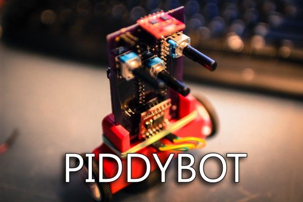
After I built the tiny balancing robot using an IR sensor for stabilization, there was a comment on the youtube video about how it would be a good thing for kids to build and learn about PID controls. I thought that was a great idea, the only problem was that that tiny robot was the simplest of balancing robots. It was just an on off switch for telling the motor which way to move. There was no actual PID implementation in that system. So that got me thinking about how it would have been really cool if in one of my classes where I was learning about control theory I had a robot that actually let you see the changes in a PID system in real time. I decided to take it upon myself to create such a robot.
The basic plan I had in my head was to make it as simple and small as possible – while making it possible for anyone to build themselves. The components consist of:
- 3 Potentiometers (might become 4)
- Arduino Nano (Obvously!)
- A custom PCB – on OSHpark – Want to Mod it before Buying? Frizting File Here
- 2 Geared Motors 26:1 or similar
- Sparkfun 1A Dual Motor Driver Board
- Wheel set – Bigger Might work Better…
- 6 DOF IMU from SparkFun
- 3D printed Body. – Thingiverse
- 2 x Battery Connectors
- 2 x Lithium Batteries 110mAh
- 4 x M2 Screws for Motor Mounting
- 2 x Female Jumper Cables
- 2 x SPDT Slide Switches
- 4 or more Right angle Headers
- A bunch of Headers.
- My PIDDYBOT Arduino Code – V3 Now with Location PID Control – PIDDYPROGRAM_V3_Upload
- Assembly Instructions… Kind Of – NEW!
First I figured out how small I could make the PCB and still have everything fit. I actually made the PCB a long time ago and it was one of the first I made, so I probably could have made it smaller; I’m happy with the size now.
For more detail: PIDDYBOT – A Self Balancing Teaching Tool

