Summary of Assembling the ZIFduino USB 1.2
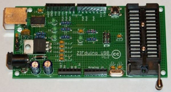
The ZIFduino is an Arduino-compatible board featuring a Zero Insertion Force (ZIF) socket, designed for prototyping and later moving the ATmega chip to standalone projects. This article guides users through assembling the kit, which includes soldering surface-mount components like the FT232RL chip, capacitors, resistors, and connectors. It details testing procedures by installing drivers and verifying COM port detection on a computer before finalizing the build.
Parts used in the ZIFduino:
- ZIFduino board
- FT232RL chip
- 47 uF radial capacitors
- 0.1 uF ceramic capacitors
- 22 pF ceramic capacitors
- 1 K ohm resistors
- 10 K ohm resistors
- 3mm T1 LEDs
- 16 MHz crystal
- 1N4004 diode
- Resettable fuse
- 7805 voltage regulator
- Pushbutton
- USB B connector
- Power jack
- 3 pin single row male header
- Shorting block
- 6 pin dual row male header
- 6 pin female headers
- 8 pin female headers
- 28 pin ZIF socket
- ATMEGA168-20PU chip
The ZIFduino, for all intents and purposes, is an Arduino with a ZIF socket. It’s geared toward those that want to do prototyping on the platform, but then move the ATMega chip to a stand-alone environment. The pin layouts are exactly the same, so it should be compatible with most shields designed for the Arduino.
The PDF of this instructable can be downloaded at bittyware.com/instructions/Assembling-the-ZIFduino-1.2.pdf
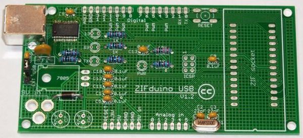
Step 1: Get the kit
The kit comes in two flavors. The board itself, and the full kit. There is also an option to have the FT232RL chip pre-soldered if you’re not comfortable working with SMT parts.
The kit can be purchased at http://www.bittyware.com.
Parts included:
(1) ZIFduino board
(1) FT232RL chip
(2) 47 uF radial capacitors
(9) 0.1 uF ceramic capacitors
(2) 22 pF ceramic capacitors
(6) 1 K ohm resistors
(1) 10 K ohm resistors
(4) 3mm T1 LEDs
(1) 16 MHz crystal
(1) 1N4004 diode
(1) Resettable fuse
(1) 7805 voltage regulator
(1) Pushbutton
(1) USB B connector
(1) Power jack
(1) 3 pin single row male header
(1) Shorting block
(1) 6 pin dual row male header
(2) 6 pin female headers
(2) 8 pin female headers
(1) 28 pin ZIF socket
(1) ATMEGA168-20PU chip
The crystal and the 22 pF capacitors are in their own separate bag to prevent mixing up the capacitors.
Step 2: FT232RL
If you chose to have it pre-mounted, you can skip this step and the next.
Solder the FT232RL in place. There are a number of great tutorials for soldering surface mount parts all over the web. SparkFun has some good ones on their tutorials page, starting about half way down.
Step 3: Test your work
I always like to test the chip before moving too much further. At this point it’ll be much easier to correct any problems.
Solder the C4 capacitor, followed by the F1 fuse, then the 3 pin male header.
Slide the shorting block onto the header, shorting the center pin with the one labeled USB.
Now solder the USB B jack in place. Solder all six pins, making sure you have a good pool of solder on the two larger pins. These are to ensure a strong mechanical connection, so be sure to fill the holes completely.
Take the board to your computer and go to http://www.ftdichip.com/Drivers/VCP.htm. There you will find the drivers needed for your platform. Extract them to the location of your choice and make a note of where they are. If you already have the drivers installed, you can skip this part.
I’m assuming a Windows environment here, but there are installation guides for others at the FTDI site.
Plug the board into your computer, and you should be greeted with the New Hardware Wizard. Point the wizard to the driver location noted above. After they’re installed, you will see a new COM port in Device manager. You’ve just successfully installed the FT232RL.
If you don’t get the New Hardware Wizard and you don’t see a new COM port in Device Manager, you’ll need to check your work. Take a look at all the pins under magnification and make sure they’re all soldered in place and you don’t have any lifted pins. Also check for solder bridges.
NOTE: There are two sets of pins that are intentionally bridged. Don’t try to remove those or you’ll have problems.
Major Components in Project(1) ZIFduino board
(1) FT232RL chip
(2) 47 uF radial capacitors
(9) 0.1 uF ceramic capacitors
(1) ATMEGA168-20PU chip
(1) FT232RL chip
(2) 47 uF radial capacitors
(9) 0.1 uF ceramic capacitors
(1) ATMEGA168-20PU chip
For more detail: Assembling the ZIFduino USB 1.2
- What is the primary purpose of the ZIFduino?
It is geared toward those that want to do prototyping on the platform but then move the ATMega chip to a stand-alone environment. - How can I purchase the ZIFduino kit?
The kit can be purchased at http://www.bittyware.com. - Can I buy the FT232RL chip pre-soldered?
Yes, there is an option to have the FT232RL chip pre-soldered if you are not comfortable working with SMT parts. - Which driver website should I visit to install software for the board?
You should go to http://www.ftdichip.com/Drivers/VCP.htm to find the drivers needed for your platform. - What indicates successful installation of the FT232RL?
After installation, you will see a new COM port in Device manager. - What should I check if the New Hardware Wizard does not appear?
You need to check your work by looking at all pins under magnification to ensure they are soldered in place without lifted pins or solder bridges. - Are there any intentionally bridged pins on the board?
Yes, there are two sets of pins that are intentionally bridged and should not be removed. - Why are the crystal and 22 pF capacitors in a separate bag?
They are in their own separate bag to prevent mixing up the capacitors.