Summary of Around the World Time Clock
This article details the construction of a 5-zone world clock using an Arduino Uno and five TM1637 displays. The project tracks global times relative to GMT, includes AM/PM indicators via LEDs, and features a touch-activated overhead light powered by a NeoPixel stick. The author explains the wiring process, component selection, and programming logic required to synchronize multiple time zones on a single board.
Parts used in the 5-Zone World Clock:
- Arduino Uno
- TM1637 displays (5 units)
- LEDs (5 units for AM/PM indicators)
- 220 Ohm resistors (5 units)
- RTC3231 Clock module
- AdaFruit NeoPixel stick or similar lighting
- Touch sensor
- Buck converter
- Frame or case (3D printed example provided)
- 12V power supply with barrel receptacle
- Arduino Uno shield (optional)
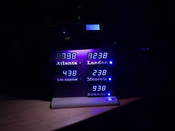
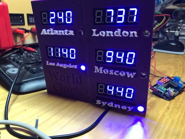
Whether world trotting or just interested in knowing what time it is before making that late night call, a 5 zone world clock fits the bill. Since I got some extra TM1637 7 digit displays in my latest shipment, I decided to put together a clock for all occasions. I decided to use an Arduino Uno for the project, which provided enough GPIO’s for 5 clocks, 5 AM indicators (LEDs) and an overhead light activated with a touch sensor. The only pin I didn’t use was D1, which is for serial Tx, which could only lead to trouble. So if you are interested, read on!
Step 1: Parts
To make the clock I used:
– An Arduino Uno (but a Nano or Mega would also work)
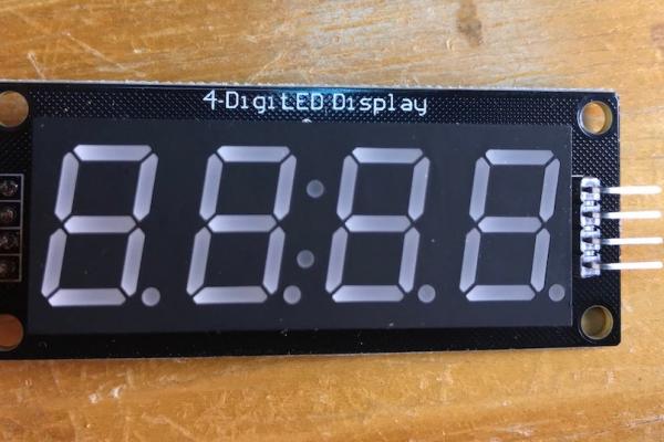
– (5) TM1637 displays
– (5) LEDs (to use as AM/PM indicators)
– (5) 220 Ohm resistors
– RTC3231 Clock
– AdaFruit NeoPixel stick or other lighting
– Touch sensor to activate light
– Buck convertor to accommodate power draw
– Frame or case (I 3D printed a case, but be creative)
– 12V power with a barrel receptacle (to allow splitting of the feeds)
– optional – Arduino Uno shield (just to make it a little simpler)
Step 2: Getting Started
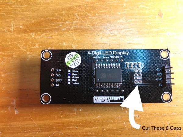
I’m still new to the TM1637 so I programmed one first to see what I could do. At first it did nothing, but the Arduino community is amazing and soon had me up and running. On my TM1637 I had to cut the 2 caps on the back to get it working and from there just some trial and error. In the end I still couldn’t get a colon for the clock – it “replaces” the hour digit in position 1, but i’m okay with it, for now.
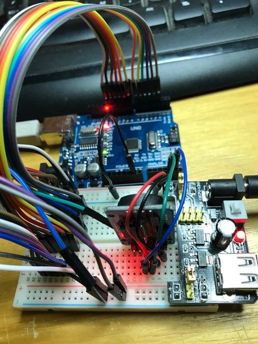
Next, wire up a breadboard with everything first to make sure all of your connections and programming match – yeah, I’m still a step by step guy. Then decide on the desired locations and setup your target locations by finding the time differences from GMT. Now on to the soldering and positioning.
Step 3: Wiring
Using a barrel power connector for the 12v input, split the power and ground to the 1) buck convertor and 2) the Vin on the Arduino.
Use the buck convertor to make 5v power and ground rows on the shield to run the connections, this will stabilize any power issues.
Each TM1637 has 4 connections (5v, Grd, Data and Clock), with the DIO and CLK going to individual GPIO pins (I used 2-11) and the power to my rows.
For the Meridian indicators (5 LEDs) solder (5) 220 Ohm res to ground and the Anode connections to A0-A3 and D12.
The RTC needs a 5v and Grd along with the SDA and SCL (A4 and A5).
The light stick needs to be grounded twice, once to the row and once to the Uno. Run the 5v to the row and data to a GPIO (D13). The touch sensor runs to 5v and Grd and to GPIO D0.
Step 4: Programming
The programming is fairly straight forward. I used the TM1637display.h library for the displays, assigning each display a unique name – predictably, with the city name. Just change the DIO and CLK pins for each.
Code your first location with the time difference and set the AM/PM perimeters for the LED to be on/off based on the hour. Use it to duplicate for each location.
I assigned the hour to position 0, 2 digits, no leading zero. For the minutes I used ‘minute’ and divided by 10 for digit 1 (pos 2, 1 digit) and modulo (%) for digit 2 (pos 3, 1 digit).
Lighting the NeoPixel with the sensor was just like any other button/LED combo using the Adafruit_NeoPixel library.
Easy.
Step 5: Assembly
Craft a suitable case that fits the displays and some room behind for the board, power input and buck convertor. Insert, attach wires, power on and it’s ready. Okay, there may be more to it than this, but those are the basics regardless of the design.
Enjoy and Happy Tinkering!
Source: Around the World Time Clock
- Can I use an Arduino Nano instead of an Uno?
Yes, the article states that a Nano or Mega would also work for the project. - How do I stabilize the power for the displays?
The author uses a buck converter to create stable 5v power and ground rows on the shield. - What pins are used for the TM1637 data and clock signals?
The DIO and CLK connections go to individual GPIO pins, specifically pins 2 through 11 in this build. - Does the RTC module require specific pins for communication?
Yes, the RTC requires SDA and SCL connections which correspond to pins A4 and A5. - How is the NeoPixel light activated?
The light stick is grounded twice and controlled by a touch sensor connected to GPIO D0. - What library is used to control the digital displays?
The TM1637display.h library is used to assign unique names to each display based on city names. - How are the minutes calculated in the code?
The code divides the minute value by 10 for the first digit and uses modulo (%) for the second digit. - Why was pin D1 not used in the project?
Pin D1 was left unused because it is designated for serial Tx, which could lead to trouble. - What should be done if the TM1637 display does nothing initially?
The author suggests cutting two caps on the back of the display before proceeding with trial and error. - How is the frame constructed for this project?
A suitable case can be crafted to fit the displays, with room behind for the board, power input, and buck converter.