Summary of Arduino Xylophone
This article details the construction of a DIY MIDI xylophone using an Arduino Mega. The project utilizes 12 piezo elements to detect strikes on acrylic bars mounted in a wooden housing. The system converts vibrations into serial data, which is then transformed into MIDI signals via software for use with music production programs.
Parts used in the Arduino Xylophone:
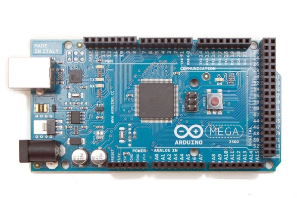
- Arduino Mega 2560
- Piezo Element
- 1M Ohm resistors
- Single Core wire
- Printed Circuit Board
- USB 2.0 Cord
- Electrical Tape
- Heat shrink
- 1/4 plywood
- 1/8 acrylic sheeting
- Wood glue
- 1/4 vinyl tubing
- 1 1/2 inch long machine screws
- 2 inch masking tape

I made a xylophone that uses an Arduino Mega to detect when a note is struck, and generate MIDI output. This project is wondeful because I essentially made a xylophone, a drumkit, and any other MIDI controlled sound instrument, with one tool. The following steps will outline what I used to make this xylophone.
Step 1: You Will Need…
To construct the xylophone I used the following parts from Radioshack:
(x1) Arduino Mega 2560 (Radioshack #276-127)
(x12) Piezo Element (Radioshack #273-073)
(x12) 1M Ohm resistors (Radioshack #271-1356)
(x1) Single Core wire (Radioshack #278-1221)
(x1) Printed Circuit Board (Radioshack #276-170)
(x1) USB 2.0 Cord (Radioshack #26-714)
(misc) Electrical Tape (Radioshack #64-2373)
(misc) Heat shrink (Radioshack #55048444)
The housing for the xylophone was easy to build. I used:
1/4″ plywood
1/8″ acrylic sheeting
wood glue
1/4″ vinyl tubing
1 1/2″ long machine screws.
2″ masking tape
Tools:
laser cutter
scissors
cotton swabs
small flat head screw driver
Step 2: Free the Piezos, Then Solder Longer Leads.

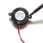
For this project, I used piezo elements to detect when each note is struck on the xylophone. These piezos detect vibration, or a knock. Often the elements come in a housing, to protect the disc from being bent or smashed – but for this project I needed to remove them from their plastic.
By gently pressing around the edges with my fingers, you could hear the glue crack apart from the plastic, I loosened the bottom of the casing. Carefully, I insterted a precision flat-head screw driver, and popped the bottom of the case off.
The piezo element could then be removed from the outside of the housing.
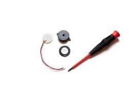
Because I am using an Arduino Mega Board, I could have up to 16 Analog inputs, or 16 Piezos. I decided to just include an octave & a half, 12 notes, so I used 12 piezos.
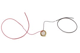
After they were free from their case, I soldered longer wires to each piezo element, to prepare them to be inserted into the xylophone. When I was done soldering longer leads on to each piezo, I wrapped my solder points with heat shrink or electrical tape.
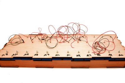
Step 3: The Bars and Housing.

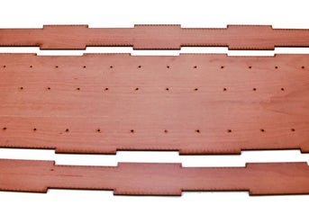
I used CorelDraw to draft vector files that would guide the laser cutter for the housing and bars of the xylophone.
The acrylic bars were each 10×2 inches. Each bar has two holes in them that will guide a machine screw through the bar, and mount to the top panel of the wooden housing.
The wooden housing I designed is 10.5x30x3 inches. It forms a shallow box that supports the electronics embedded within it. I used woodglue and a cotton swab to secure all of the corners, and allowed 24 hours to cure before I sanded down all of the edges.
The CorelDraw file for the base housing is attached to this step.
Step 4: Attach the Piezos to the Bars
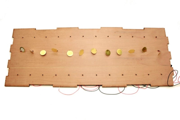
I threaded the Piezo wires through the middle holes in the top panel of the housing. Then, I centered the piezo element on each acrylic bar, and used 2 inch blue masking tape to adhere the piezo to the bar.
Step 5: Attach the Bars to the Top Panel.
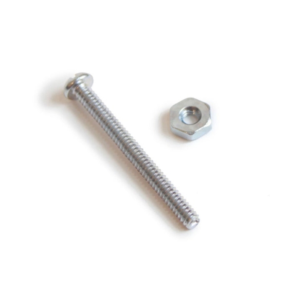
I used 1 1/2″ machine screws and nuts to secure the bars to the wooden paneling.
To prevent excessive shake or vibration on each bar, I decided to use vinyl tubing as a shock absorber on each machine screw. With 12 bars, I used 24 machine screws and nuts, and 24 3/4″ lengths of vinyl tubing. Thread the machine screw through the bar, then the vinyl, and slip it into the paneling. When the screw was through the panel, I was able to twist on the nut to fully secure it to the panel.
All of these should only be finger-tight, to avoid stress on the paneling, or on the bar.
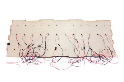
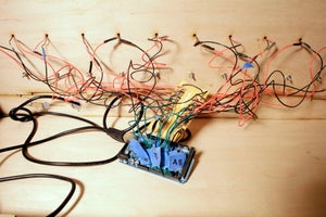
Step 6: Build the Circuit.
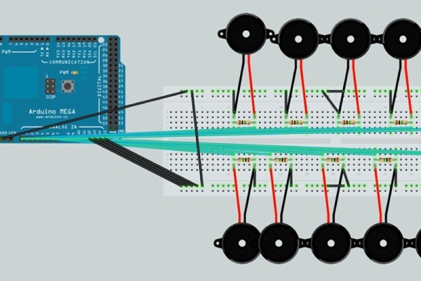
Before connecting the piezos to the Arduino, I connected a 1-megohm resistor in parallel to the Piezo element to limit the voltage and current produced by the piezo, and to protect the analog input ports on the Arduino. On the PCB, I marked with a permanent marker which piezo goes to each analog input port on the Arduino. I also made the same markings on the back of the top wooden panel.
After I soldered the resistors into place, I ran a small jumper wire from one end of the resistor, to the longest rail on the PCB, and designated it my ground rail. Next, I soldered all of the piezos’ ground wires into place, in line wtih the same end of each grounded resistor. The positive lead from the piezos is soldered in to the same rail as the other end of each resistor.
I cut 12 lengths of green wire to be my “signal wire” to the Arduino. Each signal wire is soldered into the same positive resisted rail of the piezo.
The fritzing diagram file is attached to this step.
Step 7: Connecting to the Arduino
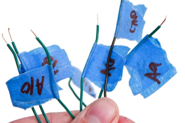
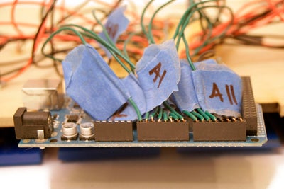
I took all of the signal wires, and the ground wire running from the PCB and marked each one with blue masking tape, writing which port each wire was designated to. I then fed all of the marked single core wire into the corresponding ports of the Arduino.
All remaining Analog ports must be grounded! Otherwise it will affect your serial output from the arduino. I used 4 black wires, running from the ground rail of the PCB directly to the open analog ports of the Mega board. (A12, A13, A14, and A15)
When you have completed your circuit, you can load the xylophone program, or sketch, onto the Arduino board from the Arduino Developing Environment.
Here is the sketch I used.
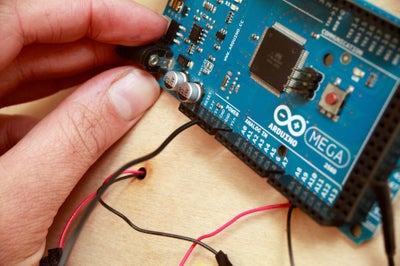
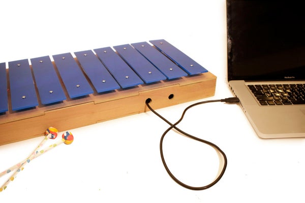
Step 8: Power and Communication.
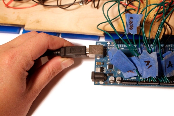
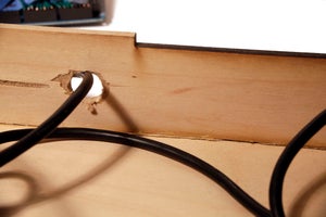
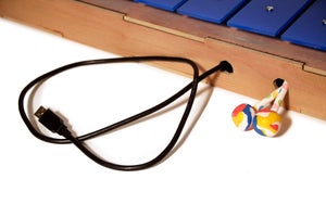
The Arduino can be powered via USB, which doubles as a communication port. I ran a USB cable through the housing of the xylophone. By drilling a small hole, that was big enough for the ends of the cable, I could hide most of the USB cord in the housing.
I drilled a second hole to hold my mallots.
Step 9: Serial to Midi
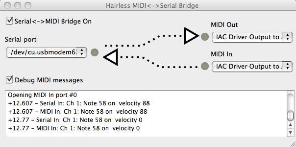
To get the xylophone coupled with my comptuer I used software called Hairless. It converts the serial out signal from the Arduino into a MIDI signal that programs like GarageBand, Logic, and Ableton can read and record. Be sure that the bridge is running before you try and import MIDI data from the xylophone.
Note: Disable the bridge while trying to update the sketch on the Arduino board. You cannot have the bridge running while trying to communicate to the board from the Arduino software.
Step 10: Jam It!
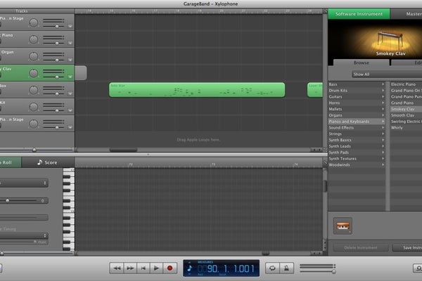
After you are up and running, you can play the xylophone like drums. Record your beat track. Then kick change the MIDI instrument to a bass synth, and record a rhythm track. Finally turn it back into a xylophone and create a melody track for the best song ever. This thing is a lot of fun!
Source: Arduino Xylophone
- How many piezo elements are used in this project?
The project uses 12 piezo elements to cover an octave and a half. - What material is used for the xylophone bars?
The bars are made from 1/8 acrylic sheeting cut to 10x2 inches. - Does the circuit require resistors connected to the piezos?
Yes, a 1-megohm resistor is connected in parallel to each piezo to limit voltage and protect the analog input ports. - What software converts the serial signal to MIDI?
Hairless software is used to convert the serial output from the Arduino into a MIDI signal. - Can the unused analog ports on the Arduino affect the output?
Yes, all remaining analog ports must be grounded to avoid affecting the serial output. - How are the bars attached to the housing panel?
The bars are secured using 1 1/2 inch machine screws, nuts, and vinyl tubing as shock absorbers. - What tool is recommended to remove the piezo elements from their plastic casing?
A precision flat-head screw driver is used to pop the bottom of the case off. - How is the Arduino powered during operation?
The Arduino is powered via USB, which also serves as the communication port.