We’ll be making a diorama presenting the water cycle, using Arduino and some motors to add movement and lighting. It has a school feel – because it is actually a school project!
The presentation scenario is this:
The sun rises in the morning [One servo motor moves the sun].
Water evaporates from the sea [One stepper motor raises the “evaporation sheet”]
Clouds form in the sky [One stepper motor lowers the cotton clouds]
Rain falls [One stepper motor lowers the “rain sheet”]
Meanwhile, lights (APA106 LEDs) change color to signify the sunrise, the cloudy sky, the lightnings during the rain.
Materials:
- Arduino Uno
- 5V Stepper Motors and drivers (x3)
- Servo Motor(x1)
- APA106 LEDs (x5)
- Metal Tube
- Screws and bolts
- Papers, tulle, cotton
- Hot glue gun
So, off we go!
Step 1: Build the Box
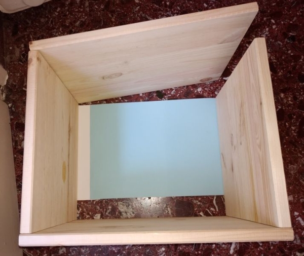
We have built a wooden box, but you can also use a carton. The box dimensions are 40cm front, 25cm depth, 30cm height.
We’ve put a handy lid with hinges, so that by lifting it up it is easier to work. Also, we don’t really need the back wall, so you can skip that and just use some blue paper for the sky, as shown in the photo.
Step 2: Attach the Motors
We will attach the stepper motors near the top of the box, so that they rotate and wrap up or down our rain tulle, evaporation tulle, and clouds.
First we need to drill holes.
Use a paper to create a mask of the motor, as shown on the photo. This will allow you to mark the holes correctly [photo]. Drill, then attach the motor with screws and bolts.
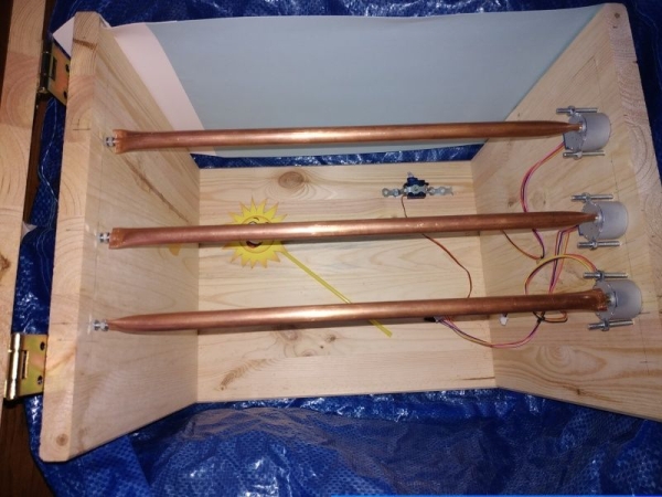
Step 3: Attach the Axes
For the axes, we are using copper plumbing tube. Measure the distance taking into account the motor depth, subtract one more cm, and cut 3 pieces.
Use the motor shaft as a mold, and use pliers to press the one end of the tube around it.
Then use a screw as a mold, and do the same on the other end of the tube.
Drill a hole at the other wall, opposite the motor shaft (measure distances). Secure the axis between the motor shaft and the screw through the hole. Use one or two bolts to secure the screw, and a metal ring to allow for smoother rotation of the axis, as shown in the photo.
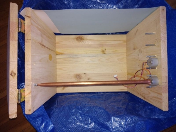
Step 4: Secure the Servo Motor
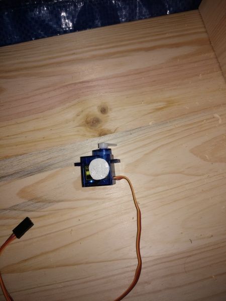
Use some blue-tac beneath, and a metal strip with screws above to attach the servo motor on the floor. This will be used for raising the sun, as shown in the photo.
Make sure you attach it in the right direction. (If you do it wrong it is not a huge problem, you can just edit it in the arduino code.)
Use a straw and glue to mount the sun on the motor shaft.
Step 5: Connect the Electronics, Motors, LEDs
The Arduino Uno has 14 digital pins. We need 4 pins for every stepper motor driver, plus one pin for the servo motor, plus one pin for the LEDs.
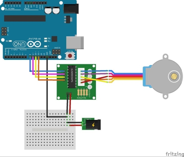
You can see the basic connection in the schematic. 4 digital pins are connected to the driver. You will need a separate power source for the driver (and motor), since motors draw quite some power and you will have problems if you power them from Arduino. You can use a USB charger and cable, cut it, use +5V and GND to power the motor. You will also need to connect the GND from the Arduino board to the GND from the external power supply, as shown in the schematic.
The connections:
Pin 0,1,2,3 : Motor 2
Pin 4,5,6,7 : Motor 1
Pin 8,*10,11,12 : Motor 0. Note that we save PIN 9 for the Servo motor: in some Arduino boards, only pins 9 and 10 can drive a Servo.
The servo motor connection is pretty standard. Use Digital Pin 9 for the control. Use the external power source, the same as for the stepper motors, to power the servo (i.e. not like, the schematic, where power is taken from the Arduino board.)
The APA106 LED design allows us to individually control several LEDS with only one pin. We will be using Digital Pin 13 (which is also connected to the built-in LED on the Arduino board). The basic connection can be seen on the schematic. APA106 has four pins. The two middle pins are for +5V and GND. Then, we connect the first LED’s DATA IN to Pin 13, its DATA OUT to the second LED’s DATA IN, etc. Every succeeding LED takes its DATA IN signal from the DATA OUT of the previous. The last LED’s DATA OUT can be left unconnected.
You might want to secure the LEDs on the case after you do the decoration, so that you can inspect the lighting better. Alternatively, you can secure them not, using hot glue, and install the decorations afterwards.
Step 6: The Arduino Code
Here is a description of what the code does.
Sunrise: The servo motor goes from 10 to 50 degrees, speed 2 degrees/sec, while the lighting changes from red-ish (dawn) to white (noon).
Vaporisation: A stepper motor winds the axis where the “vapors” tulle is attached, raising it. You might have to adjust the number of turns, depending on your dimensions.
Clouds: A stepper motor unwinds the axis to reveal the clouds. The scene colors change to a “rainy” setting.
Rain: A stepper motor unwinds the “rain” tulle axis. We have random flashes, where color changes to white for a while – and then back to “rainy”.
System reset: Lights are off, and then the motors wind back the axes, so that the system is ready to do another iteration when plugged in again.
Note that we have opted to have just a single run, and then a reset, so that we minimize the chance that someone stops the system mid-action. In that case, we would have the tulles half-winded on the axes, so the system wouldn’t run correctly.
Play with the code a bit, before adding the decorations. You will make fine-tuning adjustments later.
Read more: Arduino Water Cycle Diorama