Summary of Arduino Volume Control
This tutorial demonstrates building an Arduino UNO audio player with volume control, pause/play functionality, and an LCD display. The system uses a potentiometer to adjust volume, which is visually displayed on the screen, while a button manages playback states.
Parts used in the Arduino Volume Control Project:
- Solderless breadboard
- Standard earphones
- Analog potentiometer
- 3.5mm jack
- 16x2 LCD with I2c backpack chip
- Button
- 10 ohm resistor
- Arduino UNO with USB connector
- Solderless wires
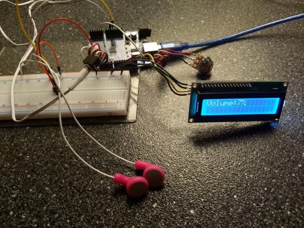
ArduinoUNO with volume control, pause/play button, and LCD display:
This tutorial will show you how to set up an arduinoUNO to produce a tone through standard earphones, with volume control via potentiometer, with visual volume display via LCD, with pause/play button.
Step 1: Pieces, Parts
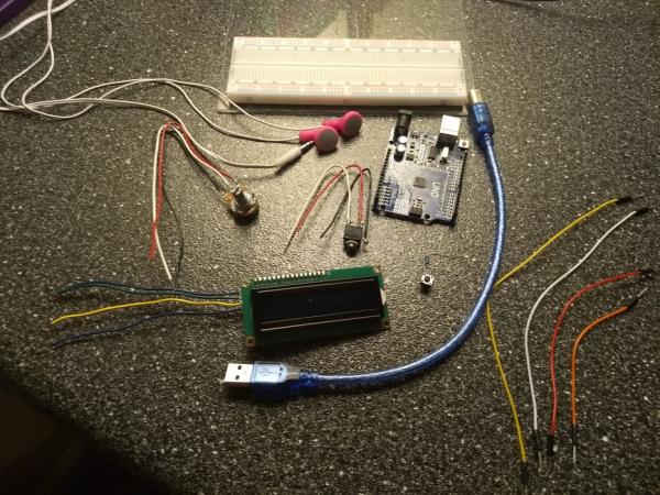
The image shows the components used in this demonstration.
-solderless breadboard (attached to acryllic base in photo)
-standard earphones
-analog potentiometer
-3.5mm jack
-16×2 LCD with I2c “backpack” chip
-button
-10 ohm resistor(shown above the button)
-arduinoUNO with USB connector
-solderless wires
Step 2: A Note About Soldering:
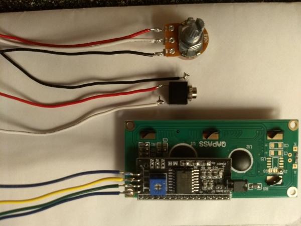
While designing this example, the solderless connections on these components were unreliable.
This demonstration does not include soldering, but it should be noted that connections have been soldered to this hardware.
-potentiometer
-3.5mm jack
-LCD
Also noteable in this image, the black I2c “backpack” chip is visible on the back of the LCD. Normally the LCD interfaces with 16 connections. One function of the I2c is to reduce this number to 4. This is where the soldered connections are made.
Step 3: Power and Ground:
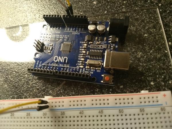
Begin by attaching power and ground connections to the solderless breadboard with the solderless connector wires.
This makes supplying power to and grounding the rest of the circuit much more manageable since there are very limited pins on the arduino.
Step 4: Pause/Play Button:

In the image, the button straddles the two halves of the breadboard. This is just to leave plenty of space.
The 10ohm resistor is connected to the ground rail and one side of the button.
Another solderless connector wire connects the other side of the button to the power rail.
Step 5: Connect the LCD:
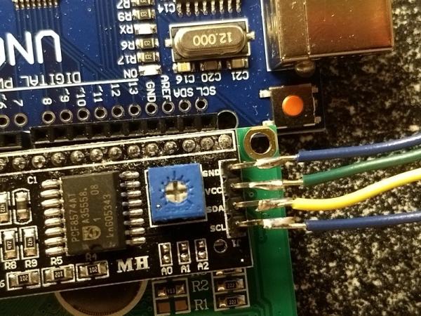
The Ic2 chip and the arduino are both labeled to help identify where connections belong.
SDA and SCL (blue and yellow) connect to the ardunio in the pins labeled the same.
GND and VCC are ground and 5v respectively. Connect them to the ground and power rails on the breadboard.
Source: Arduino Volume Control
- How does the project display volume?
The project uses a 16x2 LCD with an I2c backpack chip to provide a visual volume display. - What component controls the volume level?
An analog potentiometer is used to control the volume via the standard earphones. - Can this project be built without soldering?
The demonstration uses solderless connections for the final build, though the author notes that soldering was used for the potentiometer, jack, and LCD during design. - Why is an I2c backpack chip used with the LCD?
The I2c chip reduces the required interface connections from 16 down to 4. - Which pins connect the LCD SDA and SCL lines?
The blue SDA and yellow SCL wires connect to the corresponding labeled pins on the Arduino. - How is the pause/play button wired?
A 10 ohm resistor connects the ground rail to one side of the button, while a wire connects the other side to the power rail. - What is the purpose of attaching power and ground to the breadboard first?
This step makes supplying power and grounding the rest of the circuit more manageable due to limited Arduino pins. - Does the article recommend soldering for beginners?
The article states that solderless connections were unreliable during the design phase but presents a non-soldered demonstration setup.