For our second project, I wanted to make something that I am going to be able to use in my day to day life. When I have to leave during awkward mealtime hours, it’s important for my dog to maintain a consistent eating schedule, and this device will allow me to have him fed even if I’m not present. It is a Servo motor connected to an Arduino, with three buttons controlling it. These buttons correspond to the delay time, with the possible options being a one hour delay, a two hour delay, or a four hour delay.
Step 1: Prototype
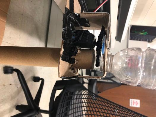
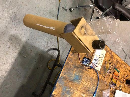
When I created my prototype, I did not have a specific plan in mind. I ended up liking the layout and the general design, although there were a few flaws. From the gif you are able to see the food run through pipe as the Servo motor turns the ‘stopper’. The problem with this was that the head of the Gatorade bottle was not wide enough to allow all the food to pass through. Additionally, there were many food pieces all over the floor because the bottom tube was not big enough for the food to pass straight food. Lastly, when thinking of my final design, I took into account the quality of materials used. I knew that cardboard would not last long, and something like wood may allow my project to be used for years to come.
Step 2: Design
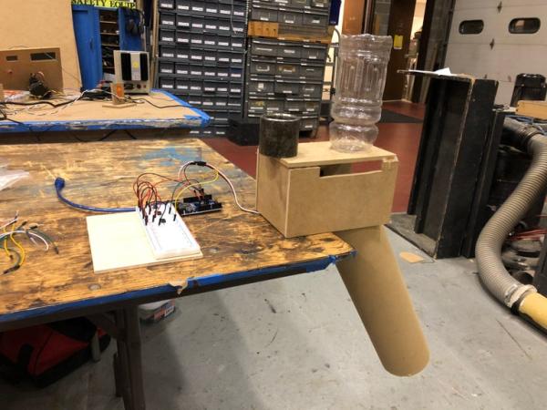
When I started my design, I knew that it would be much more important to take specific measurements for the final product. I was able to make the corrections I needed to through more careful planning. I cut the head of the Gatorade bottle, allowing the food to pass through seamlessly. The larger exit tube made it much easier for the food to travel without spilling. Measuring this more precisely gave me the opportunity to put the ‘stopper’ practically touching the top of the wood housing, plugging the hole much better than in the prototype. Although my prototype more or less functioned how I envisioned, being able to upgrade my materials for the final version allowed my project to become much improved, adding both aesthetic appeal and higher functionality.
Step 3: Arduino
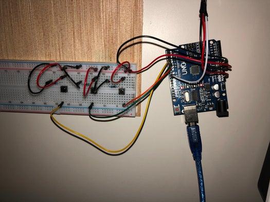
Although my project has two different Arduino functions, the hardware portion was not difficult to complete. I separately wired the Servo and the three buttons following the schematics shown on the Arduino website, which made it easy for me to visualize the different components. I added a schematic of my Arduino connected to the same Breadboard that I have, an included a servo, which in the schematic has no purpose, for reference.
Step 4: Code
#include
Servo myservo;
const int buttonPin1 = 7;     // the number of the pushbutton pin
const int buttonPin2 = 6;     // the number of the 2nd pushbutton pin
const int buttonPin3 = 5;     // the number of the 3rd pushbutton pin
// variables will change:
int buttonState1 = 0;        // variable for reading the pushbutton status
int buttonState2 = 0;        // variable for reading the pushbutton status
int buttonState3 = 0;        // variable for reading the pushbutton status
int pos = 0;                 // variable to store the servo position
void setup() {

  myservo.attach(9);

}
void loop() {
  myservo.write(0);
  buttonState1 = digitalRead(buttonPin1);
  if (buttonState1 == HIGH){
    delay(3600000);
    myservo.write(90);
    delay(10000);
    myservo.write(0);
  buttonState2 = digitalRead(buttonPin2);
  if (buttonState2 == HIGH){
    delay(7200000);
    myservo.write(90);
    delay(10000);
    myservo.write(0);}
  buttonState3 = digitalRead(buttonPin3);
  if (buttonState3 == HIGH){
    delay(14400000);
    myservo.write(90);
    delay(10000);
    myservo.write(0);}
  }}
Source: Delayed Dog Feeder