Summary of Arduino Uno – Programming With A Serial Port
The article explains how the Arduino Uno's USB programming interface (via an ATMEGA16U2) can be bypassed to program the ATMEGA328P directly using a PC RS232 serial port. The author removed RN4 and C5, wired DB9 pins 2,3,4,5 to RX/TX/DTR/GND, and used an RS232-to-TTL converter (MAX202) plus a small capacitor between DTR and Reset to enable auto-reset for bootloader uploading.
Parts used in the Arduino Uno RS232 programming project:
- Arduino Uno board (with ATMEGA328P and ATMEGA16U2)
- DB9-F serial port connector
- Jumper wires
- RS232 to TTL converter IC (MAX202 used)
- 0.1uF capacitor (0.01uF used successfully)
- Resistor network RN4 (removed and saved)
- Capacitor C5 (removed and saved)
- Optional 1K ohm resistor (to restore ON LED when RN4 removed)
I’m working on an Arduino clone. The Arduino is essentially an ATMEGA328P development board with a bootloader pre-loaded. There are a lot of custom macros built into the programming interface that make it really easy to use, and even easy to build some powerful applications. Arduinos have taken off and can be found everywhere, doing everything. The hardware and software is open-source which seems to have really contributed to the product’s success.
Anyway, I was looking over the schematic of the Arduino Uno. I noticed the programming interface, which is USB, made use of another Atmel microcontroller (the ATMEGA16U2). This is the small surface mount IC in the upper left corner of the picture above. In fact most of the components in the upper left of the board are associated with programming. I figure these parts probably cost in the area of $4-$6 to add to the board, which is likely 1/3 of the entire manufacturing cost.
It seemed redundant and costly to have two microcontrollers on the board. Especially since the bootloader appears to be a simple serial interface. I suspect that I understand why the Arduino Uno people went the two microcontroller route. First, new computers don’t have a serial port anymore. So a USB interface is just easier for the customer. Second, the cost of the microcontroller and surrounding components is about the same as a dedicated USB-232 converter IC. It might even be less expensive, although there would be some NRE (non-recurring engineering) costs.
This all left me wondering if I could replace all of the USB to conversion on the board and just use an RS232 to logic level converter chip to program the Arduino Uno with my PC. If so, then the programming interface circuitry drops to about $0.80 in small quantities.
It turned out that this was pretty easy to do. So here’s what I did.
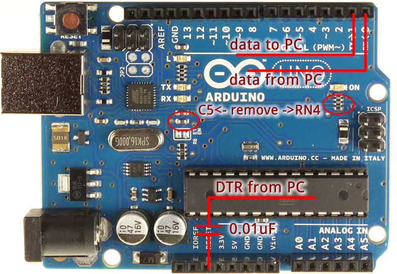
1. Connect jumper wires to pins 2,3,4, and 5 of a DB9-F serial port connector. Pin two is data from the PC, pin 3 is data to the PC, pin 4 is the DTR signal used to reset the Arduino, and pin 5 is ground. Ground should be common to all circuits.
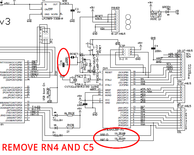
2. Remove RN4 and C5 which connect the ATMEGA16U2 (programmer) to the ATMEGA328P (Arduino). Keep these parts so you can put them back on later. Also, since RN4 is a resistor array removing it also prevents the green “ON” LED from lighting. You could solder a 1K ohm resistor across the 2 pads closest to the LED if you wanted it to light up when power is applied.
3. Connect an RS232 converter IC (I used a MAX202) between the DB9-F and the Arduino RX, TX, and Ground connections. Connect a 0.1uF capacitor between the DTR logic level output the RS232 IC and the Reset pin on the Arduino. I actually used a 0.01uF cap, since it was what I had handy, and it worked as well.
For more detail: Arduino Uno – Programming With A Serial Port
- Can I program an Arduino Uno using a PC RS232 serial port?
Yes, by wiring DB9 pins 2, 3, 4, and 5 to the Arduino and using an RS232-to-TTL converter IC you can program the ATMEGA328P directly. - What DB9 pins are required to program the Arduino?
Use pin 2 for data from the PC, pin 3 for data to the PC, pin 4 for DTR to reset the Arduino, and pin 5 for ground. - Do I need to remove any parts from the Arduino board?
Yes, remove RN4 and C5 that connect the ATMEGA16U2 to the ATMEGA328P and keep them to reinstall later if desired. - Which RS232 converter IC did the author use?
The author used a MAX202 RS232 to TTL converter IC. - Is a capacitor needed between DTR and Reset?
Yes, a small capacitor is connected between the DTR logic output of the RS232 IC and the Arduino Reset pin; the author used 0.01uF though 0.1uF is typical. - Will removing RN4 affect the Arduino LED?
Yes, removing RN4 prevents the green ON LED from lighting; adding a 1K ohm resistor across the two pads nearest the LED will restore it. - Why did the Arduino Uno originally use a second microcontroller for USB?
Because modern PCs lack serial ports and using an ATMEGA16U2 provides a USB interface similar in cost to a dedicated USB-232 converter and offers flexibility.