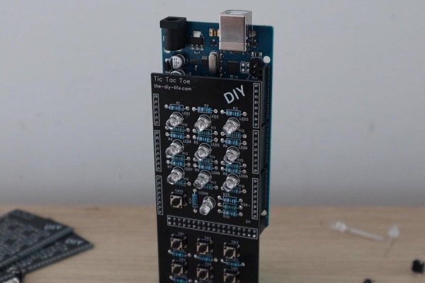
In this Instructable, we’re going to be making a Tic Tac Toe or Noughts and Crosses shield for an Arduino that allows you to play against another person or an AI player running on the Arduino.
The game board is made up of a 3×3 grid of RGB LEDs that light up green or blue to indicate the noughts or crosses. A tactile pushbutton keypad at the bottom of the shield that corresponds to the game board positions allows you to input each move. Finally, an RGB status LED shows you which player’s turn it is and allows you to select one of the three game modes using the keypad and the start button alongside it.
The 3 selectable game modes include one which allows you to play against another person, one which allows you to play against an easy level AI and one which allows you to play against an expert AI. The expert-level AI is basically impossible to beat. The best you can hope for is a draw.
If you enjoy this Instructable, please consider voting for it in the Arduino contest.
Supplies
To make your own Tic Tac Toe shield, you’ll need the following components:
- Arduino Mega – https://amzn.to/3gNaK29
- 10 x Tactile Pushbuttons – https://amzn.to/3vD9Oms
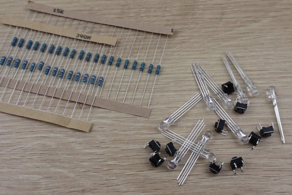
- 10 x 5mm RGB LEDs (Common Cathode) – https://amzn.to/3iUmq5Z
- 10 x 15K Resistors – https://amzn.to/3iUmq5Z
- 11 x 390Ω Resistors – https://amzn.to/3iUmq5Z
- 10 x 470Ω Resistors – https://amzn.to/3iUmq5Z
- Male Pin Header Strips – https://amzn.to/2VrQvML
The above parts are affiliate links. By purchasing products through the above links, you’ll be supporting my projects, with no additional cost to you.
Step 1: How the AI Algorithm Works
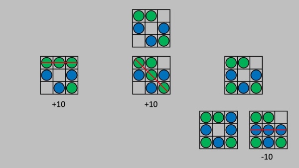
The AI works on a minimax algorithm, which is a recursive algorithm aimed at minimising the possible loss for a worst-case scenario. It’s an old algorithm that has been around since the early 1900s and can be applied to many two-player, turn-based games. It’s commonly used in computer-based chess games to this day.
The algorithm works by calculating the value of each state of the game by looking at all of the possible outcomes following each move. A move that results in the AI winning is given a score of 10 and one which results in the opponent winning is given -10. A state which results in a draw is given 0. The AI then plays the move that it calculates to be the best at reducing the possibility of the opponent winning.
With the AI running the minimax algorithm on the Arduino, it’ll always play the best possible move, so regardless of who starts, you won’t be able to beat it.
To make the game a bit more fun, as it’s not much fun losing or drawing games all the time, I’ve added a second mode that plays random moves for the first two plays before allowing the AI to finish off the game. This drastically reduces the AI’s ability to win and you’re left with the possibility of winning most games that you start and a fair number of games that the AI starts.
Step 2: Designing the PCB
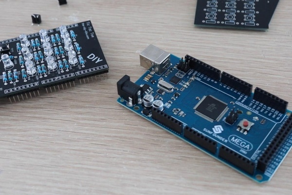
There are ways to use addressable LEDs to condense the IO to fit onto an Arduino Uno, but I already had a bunch of these RGB LEDs and an Arduino Mega lying around, so that’s what I used for this project. The shield makes use of 21 digital outputs for the LEDs and 10 digital inputs for the pushbuttons.
Make sure that you get common cathode RGB LEDs as this leg of the LED is tied to GND on this shield. If you get or have common anode LEDs then you’ll need to amend the PCB design to accommodate this change.
I sketched the circuit in Easy EDA and then designed a PCB as a shield that clips onto an Arduino Mega. Each pushbutton has a corresponding 10-20K resistor and each LED has a 220-500 ohm resistor in series with it. I used slightly higher resistors for the green legs of the LEDs as I find these are usually brighter than the blue and red legs. I didn’t connect the red legs of the LEDs on the gameboard as you only need to indicate two on states for each position.
I got these PCBs made up by PCB Way, you can get 5 basic PCBs made up for just $5 and they’ll be done in 2-3 working days.
You can download my gerber files for the PCB if you’d like to get your own made up.
Step 3: Assembling the Shield
Once the PCBs arrive, I got to assembling them.
I used 15K resistors for the switches, 390-ohm resistors for the blue and red LEDs, and 470-ohm resistors for the green LEDs. As mentioned before, using higher value resistors on the green LEDs helps to reduce the brightness so that they’re similar to the blue and red ones.
If you don’t have these specific values, you can use 10-20k resistors (or a little over/under these values) for the switches and 220-500 ohm resistors for the LEDs. Try to use the same value for each group though, don’t use different values for each of the greens, etc as you’ll then have different brightness LEDs which may be noticeable.
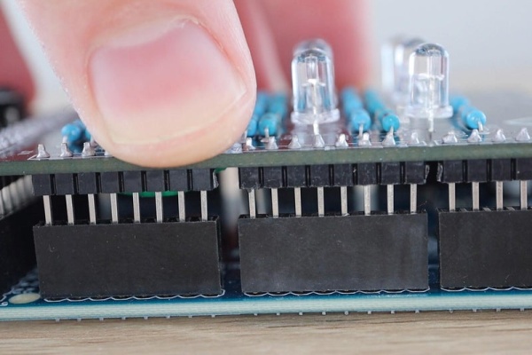
I also added some header strips to plug into all of the pins on the Arduino so that the shield is held in place firmly.
Step 4: Programming the Arduino
With the shield complete, we can plug it into our Arduino and get started with the programming.
I started out by getting a game board set up in a 3×3 array and adding some logic to get the two-player mode working. This allowed alternating green and blue inputs until the board was full or one player had won across the rows, columns or two diagonals.
Once this was working I got started on the AI’s minimax algorithm. If you’ve ever used this algorithm before then you’ll probably know that it’s not that easy to debug. It took me a couple of hours to get it working, and it finally started producing meaningful results.
I had to add some simple logic to the first AI move in order to reduce the first move’s processing time. The Arduino, being a relatively slow computer, was taking a significant amount of time to work through all 255,168 possible game outcomes if it was to play the first move and was also taking a while to play the second move.
The AI essentially now plays a corner as its first move, unless it goes second and the human player has already played a corner, in which case it plays the center position. This logic reduces the number of game plays to a couple of thousand, which the Arduino has no problem calculating in a few milliseconds. You’ll notice in the video at the beginning that the Arduino takes a bit longer on the initial moves as it is “thinking” through all of the possible game moves before playing. Near the end, there are a lot fewer possible moves to play, so decisions are made much quicker.
Once the AI player was working, I added a final game mode that just chooses random board positions for its first two moves and then allows the AI to take over. This results in a game that you can quite easily win if you play first and still allows the AI to occasionally win if it goes first or if you make a silly mistake. You could also add a fourth mode that only randomly places the first AI move. This would increase the difficulty quite a lot but still allow you some chance of winning if the AI got unlucky with the placement of this move.
I then added a start animation and code to highlight or flash the winning lines.
You can download the final version of my code here.
Step 5: Playing Tic Tac Toe on the Shield
To play a game, you first need to select one of the green game modes. These are selected using the centre top and bottom buttons on the gamepad to cycle through modes and the start button to confirm your selection. The modes are indicated on the RGB status LED:
- Green – Easy AI
- Red – Expert AI
- Blue – Two Player Mode
Once in a particular mode, the game will continue playing in this mode until reset. This allows you to automatically keep playing new games without having to re-confirm the game type each time.
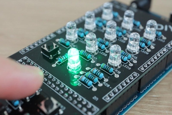
You can then play out your game and the Arduino will highlight a winning line once reached or will flash the whole game board if it is a draw.
Let me know what you think of the game in the comments section below. If you like this Instructable, please consider voting for it in the Arduino contest. Good luck building your own Tic Tac Toe shield!
Source: Arduino Tic Tac Toe Shield With an AI Opponent