Summary of Arduino Switch (case) Statement, used with serial input
This guide shows using a switch statement on an Arduino to light one of five LEDs based on a character received via serial. Sending a, b, c, d, or e lights the corresponding LED on pins 2–6; any other character turns all LEDs off. The circuit uses five LEDs with 220 ohm resistors, connected to digital pins 2–6. Open the Serial Monitor to send characters and observe LED responses.
Parts used in theArduino Switch (case) Statement Project:
- Arduino Board
- LED (x5)
- 220 ohm resistor (x5)
- Breadboard
- Hook-up wire
- USB cable to connect Arduino to computer
An if statement allows you to choose between two discrete options, TRUE or FALSE. When there are more than two options, you can use multiple if statements, or you can use the switch statement. Switch allows you to choose between several discrete options.
This guide demonstrates how to utilize a switch to activate one of multiple LEDs depending on a received byte of data through serial communication. The drawing pays attention to serial input and activates a separate LED for the letters a, b, c, d, or e.
Circuit
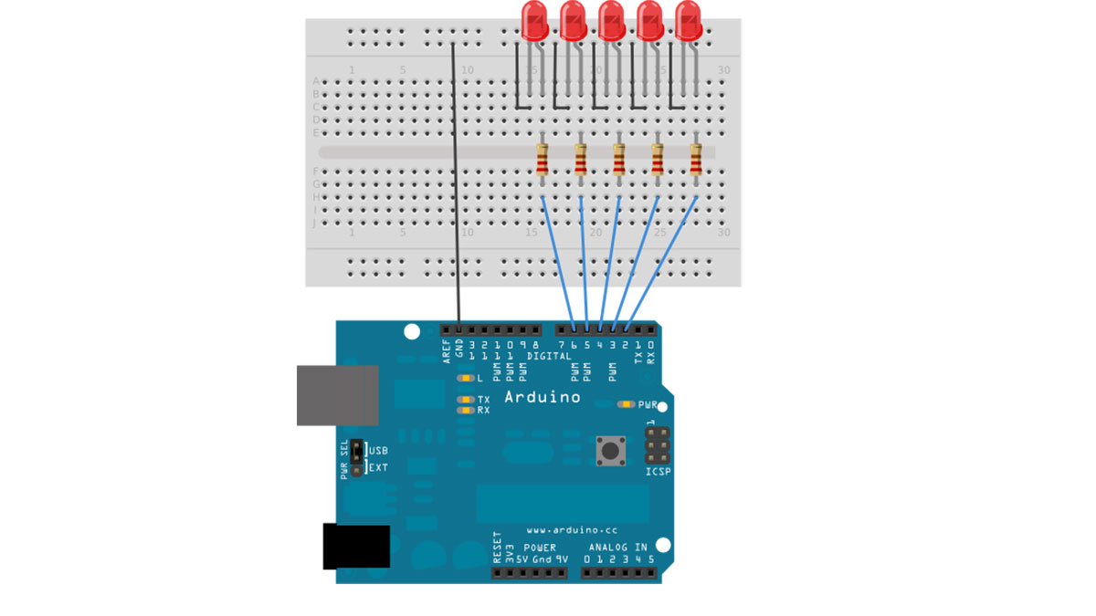
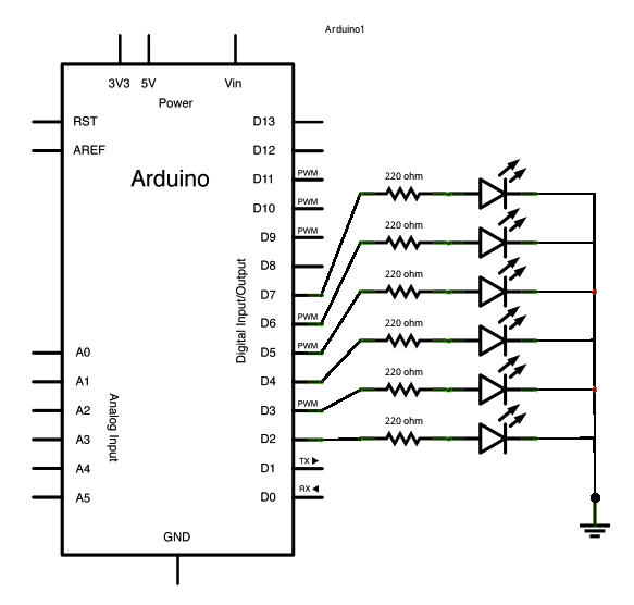
Five LEDs are attached to digital pins 2, 3, 4, 5, and 6 in series through 220 ohm resistors.
To make this sketch work, your Arduino must be connected to your computer. Open the Serial Monitor, and send the characters a, b, c, d, or e, or anything else.
image developed using Fritzing. For more circuit examples, see the Fritzing project page
Schematic:
Code
/*
Switch statement with serial input
Demonstrates the use of a switch statement. The switch
statement allows you to choose from among a set of discrete values
of a variable. It’s like a series of if statements.
To see this sketch in action, open the Serial monitor and send any character.
The characters a, b, c, d, and e, will turn on LEDs. Any other character will turn
the LEDs off.
Hardware Required
- Arduino Board
- (5) LEDs
- (5) 220 ohm resistors
- breadboard
- hook-up wire
For more detail: Arduino Switch (case) Statement, used with serial input
- How do you trigger different LEDs in this project?
Send the characters a, b, c, d, or e over the Serial Monitor; each character lights its corresponding LED. - Can other characters do anything in this sketch?
Yes; any character other than a, b, c, d, or e turns all LEDs off. - What pins are the LEDs connected to?
The five LEDs are attached to digital pins 2, 3, 4, 5, and 6. - Do the LEDs require resistors and what value?
Yes; each LED is in series with a 220 ohm resistor. - How do you send characters to the Arduino?
Open the Serial Monitor in the Arduino IDE and type/send the desired character. - Is a physical connection to a computer required?
Yes; the Arduino must be connected to your computer to use the Serial Monitor. - What programming construct is demonstrated in the sketch?
The sketch demonstrates the use of a switch statement to select among discrete values. - What happens if you send the character b?
The LED wired to the digital pin assigned for b will be turned on.