Summary of Arduino Street Traffic Light – Breadboard Edition
This article guides users through building a breadboard-based Arduino traffic light. It covers setting up the Arduino environment, understanding digital vs. analog pins, and wiring components like LEDs and resistors. The project assumes prior knowledge of basic electronics and requires a clean workspace. A future version for a more realistic setup is mentioned.
Parts used in the Arduino Street Traffic Light:
- Computer with Internet Access
- Arduino Uno
- USB A/B Cable
- Breadboard (Half-Size, with Voltage Rails)
- Red LED
- Yellow LED
- Green LED
- 3 x 100 Ohm Resistors
- 4 x Breadboard Wires (22 AWG)
Build a simple Arduino powered Traffic Light with us! This instructable is meant to walk you through almost every step, but there are a few assumptions. Read over the intro and the first step to make sure you are fully prepared! This is the breadboard version, a more realistic traffic light will be generated soon. Please leave comments – tell us if things are confusing!
Other Helpful Things:
– Good lighting
– A clean workspace
– An hour of your time
– Someone awesome to work with
Missing Something?
– Check out hackerspaces.org for a local place for tools, supplies, etc.
– Near Ann Arbor, MI? We have all the supplies needed to do this instructable at our hackerspace “All Hands Active”
– Radioshack, AdaFruit, SparkFun, Jameco, are just a few resources that will have all the needed items.
You wanted a smarter traffic light?
– That’s our next instructable, stay tuned!
Step 1: Set Up the Arduino Environment
This instructable makes many assumptions! Some people like to call these “prerequisites”. In order to make sure you get the most out of this instructable, you should have:
– The Arduino Software downloaded and installed on your computer.
– Plugged in and tested your Arduino by following the installation guide appropriate for your computer.
– Approximately one hour of time to spare, and a nice clean workspace with plenty of lighting.
Mission Complete? Continue on!
Image Source: The Getting Started w/Arduino Guide
Step 2: Wire your Green LED
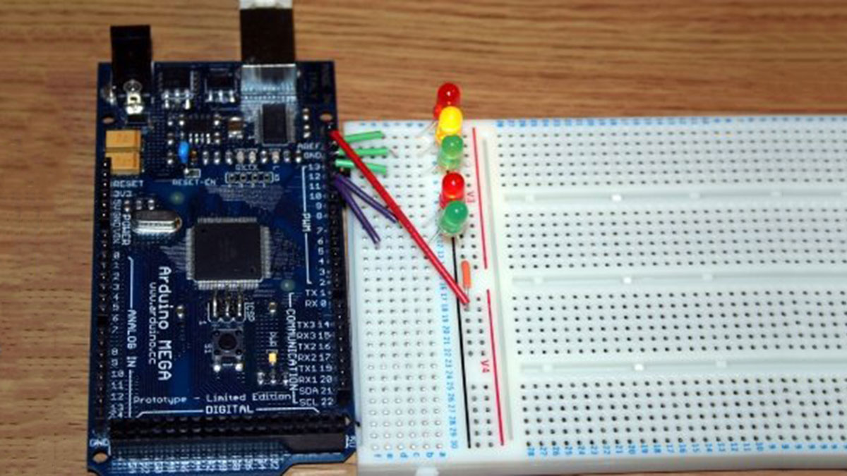
Situate your Arduino on the left, and your breadboard on the right! If you have not used a breadboard before, it’s a bit like playing Battleship. If you haven’t played Battleship, that’s okay : )
For this step, you will need:
1 x Arduino Uno
1 x Breadboard (Preferably Half-Size with Voltage Rails)
1 x 100 Ohm Resistor (Brown Black Brown)
2 x Breadboard or Jumper Wires (22 awg approx. 6″ long)
1 x Green LED
Onward!
Breadoards are great, and they come in all shapes and sizes. They make it easy for you to prototype an electrical circuit without having to solder connections together. Don’t worry if yours is a little different. If it comes with voltage rails, then it should be pretty easy to follow along. If it doesn’t, you will have to figure out an alternate way to supply power.
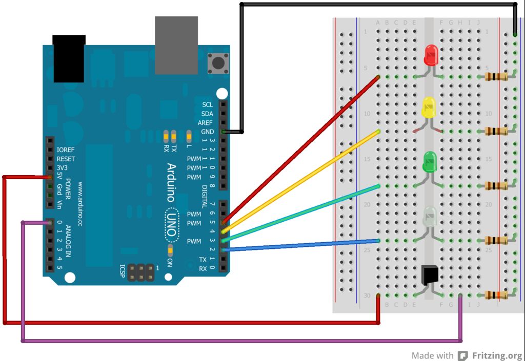
Voltage rails are the two columns that run along the left and right sides of the breadboard pictured above. These are used to make it easier to bring power to various points throughout your breadboard. We will ground all of our connections along the right, or “blue” labeled voltage rail. In the step above, w connect a black wire running from the “GND” pin of the Arduino, to a voltage rail..
Digital, Analog The Arduino has 14 Digital pins, and 6 Analog pins. A Digital pin can operate in two ways: On, also known as “HIGH”, and Off, otherwise known as “LOW”. When a Digital Pin is set to On, 5 volts of electricity are running through it. When it’s set to Off, no voltage runs through it. This will make it easy for us to turn an LED on or off. These pins are represented as “DIGITAL”, pins 0 through 13 at the top right of the Arduino pictured above.
Analog pins can operate differently. Instead of being limited to on or off, they can read a range of values from between 0 Volts and 5 Volts, but they convert “volts” into whole numbers, specifically 0 through 1023. For example: 0 = 0 Volts, 512 = ~2.5 volts, and 1023 would mean 5 volts. These pins are represented as “ANALOG IN”, pins 0 through 5 at the bottom right of the Arduino pictured above.
Resistors do exactly as they say, they resist! But what? Electrons! Too much power, or current and we can ruin our LED, so we include a resistor in line with it. We measure resistance in units called “Ohms”. The resistor we are using provides 100 Ohms of resistance. The colored strips Brown (1), Black (0), Brown (add 1 more 0), are how we identify what the value of our resistor is.
Follow the images to complete this step, then move on to the next step to get your LED turned on!
1 x Computer with Internet Access
1 x Arduino Uno
1 x USB A/B Cable for connecting the Arduino to your PC
1 x Breadboard (Half-Size, with Voltage Rails)
1 x Red LED
1 x Yellow LED
1 x Green LED
3 x 100 Ohm Resistors (Brown Black Brown)
4 x Breadboard Wires (22 AWG, approx. 6+ inches in length)
For more detail: Arduino Street Traffic Light – Breadboard Edition
- What prerequisites are needed before starting?
You must have the Arduino Software downloaded and installed, your Arduino plugged in and tested, approximately one hour of time, and a clean workspace with good lighting. - How do you identify the value of the resistor used?
The resistor value is identified by colored strips where Brown represents 1, Black represents 0, and Brown adds another zero, resulting in 100 Ohms. - Can Analog pins be used to turn an LED on or off?
No, Digital pins operate in On or Off states suitable for LEDs, whereas Analog pins read a range of values from 0 to 1023. - Where should power connections be grounded on the breadboard?
All connections should be grounded along the right side voltage rail, which is often labeled blue. - Why is a resistor included in the circuit with an LED?
A resistor is included to resist electron flow because too much power or current can ruin the LED. - What is the voltage output when a Digital Pin is set to On?
When a Digital Pin is set to On, 5 volts of electricity run through it. - How many Digital pins does the Arduino have?
The Arduino has 14 Digital pins located at the top right. - Are there resources available if I am missing supplies?
Yes, you can check hackerspaces.org, local hackerspaces like All Hands Active near Ann Arbor, or retailers like Radioshack, AdaFruit, SparkFun, and Jameco.