
Summary of Arduino-Square with Color LCD
This article guides users in assembling a Color-LCD application using the B-Squares modular platform. It details hardware and software requirements, followed by a three-step process: configuring the Arduino-Square with the LCD Shield and FTDI connector, uploading the specific sketch via Arduino Software while adjusting for driver variations, and finally reassembling the unit with a Battery-Square for power.
Parts used in the B-Squares Color-LCD Application:
- Arduino-Square
- Battery-Square
- Color LCD Shield
- FTDI USB connector (3.3V)
- USB cable
In this B-Squares App we will cover how to assemble a simple Color-LCD Application using the Arduino-Square.
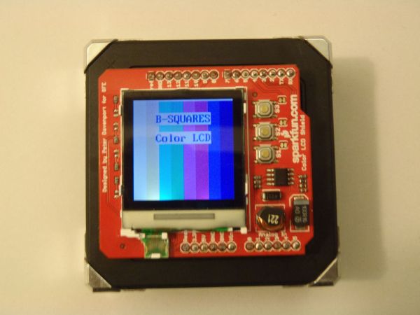
Hardware:
1. Arduino-Square.
2. Battery-Square
3. Color LCD Shield.
4. FTDI USB connector (3.3V).
Software:
1. Arduino Software.
2. BSQ-ColorLCD sketch files.
Step 1: Configure Arduino-Square
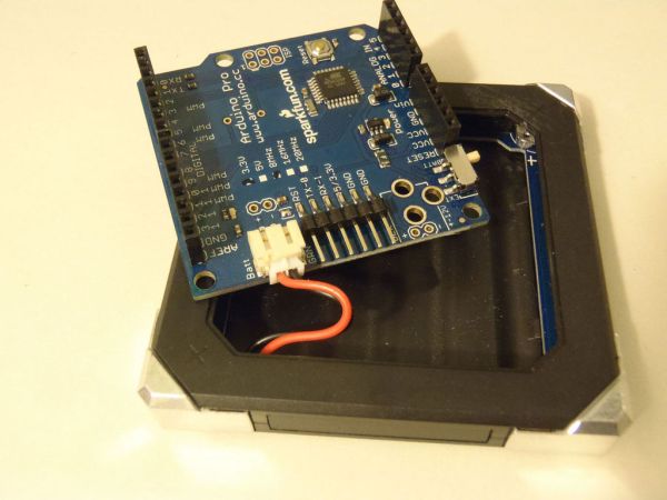
• First begin by pulling the Arduino-Pro board outside of the Arduino-Square frame and rest it on top of the frame. (You should be able to do this easily by angling the Arduino-Pro board inside the frame, pulling one side out of the frame and then the other.)
• Line up the Color-LCD Shield pins with Arduino-Pro connectors. There are 2 sets of 6 pin connectors on one side and 2 sets of 8 pin connectors on the other.
• Plug the FTDI serial adapter into the right angled 6 pin connector located on the Arduino-Pro board adjacent to the power connector.
• Plug the USB cable into your computer.
Step 2: Upload Sketch
• To install the Color-LCD library copy and paste the entire “ColorLCDShield” folder into the Arduino Library folder
o Win: My Documents\Arduino\libraries\
o OS X: ~/Documents/Arduino/libraries/
• Start the Arduino software and open the BSQ-ColorLCD sketch.
• To configure Arduino for your Arduino-Square select Tools->Board and select “Arduino Pro or Pro Mini (3.3V, 8Mhz) w/ ATmega 328”
• Go to Tools->Serial Port and select the Serial Port that was created for the FTDI serial port adapter (example “COM 5”).
• Click on the “Upload” button. You should see a small progress bar at the bottom right of the Arduino console.
• Once the code is done uploading an image with multiple colored bars should appear on your LCD Shield. NOTE: If the screen turns on but the image is distorted, the most likely reason is that your Shield uses a different driver. To fix this, change the code on line 33 from “ lcd.init(EPSON);” to “ lcd.init(PHILLIPS);” or vice versa.
Step 3: Final Assembly
• Unplug the FTDI serial adapter from the Arduino-Pro and, with the Color-LCD Shield still plugged in.
• Reinsert the Arduino-Pro board back into the Arduino-Square frame.
• To power the Arduino-Square with the Battery-Square connect the corner contacts with the “+” symbol.
For more detail: Arduino-Square with Color LCD
-
How do I configure the Arduino-Pro board?
Pull the board out of the frame at an angle, align the Color-LCD Shield pins with the connectors, and plug the FTDI adapter into the right-angled 6-pin connector. -
Where should I place the ColorLCDShield folder?
Copy the entire folder into the Arduino Library directory located in My DocumentsArduinolibraries on Windows or ~/Documents/Arduino/libraries on OS X. -
Which board setting must be selected in the Tools menu?
Select "Arduino Pro or Pro Mini (3.3V, 8Mhz) w/ ATmega 328" under Tools->Board. -
What indicates a successful code upload?
An image with multiple colored bars should appear on the LCD Shield after the upload progress bar completes. -
How can I fix a distorted image on the screen?
Change line 33 in the code from lcd.init(EPSON) to lcd.init(PHILLIPS) or vice versa if the shield uses a different driver. -
How do I power the assembled unit?
Connect the corner contacts marked with the plus symbol between the Arduino-Square and the Battery-Square. -
Can I build this project without a computer?
No, you must use a computer to run the Arduino Software and upload the BSQ-ColorLCD sketch files.
