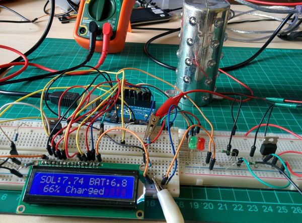
In my previous instructable, I described the details of energy monitoring of an off-grid solar system. I have also won the 123D circuits competition for that. You can see this ARDUINO ENERGY METER.
Please vote for me…..
In solar power systems, the charge controller is the heart of the system which was designed to protect the rechargeable battery. In this instructable, I will explain the PWM charge controller.
In India, most of the people are living in rural areas where the national grid transmission line is not reached till now. The existing electric grids are not capable of supplying the electricity needed to those poor renewable energy sources ( photo voltaic panels and wind-generators) are the best option I think. I know better about the pain of village life as I am also from that area. So I designed this DIY solar charge controller to help others as well as for my home. You can’t believe it, my homemade solar lighting system helps a lot during the recent Cyclone Phailin.
Solar power has the advantage of being less maintenance and pollution free but its main drawbacks are high fabrication cost and low energy conversion efficiency. Since solar panels still have relatively low conversion efficiency, the overall system cost can be reduced using an efficient solar charge controller which can extract the maximum possible power from the panel.
What is a Charge Controller?
A solar charge controller regulates the voltage and current coming from your solar panels which is placed between a solar panel and a battery. It is used to maintain the proper charging voltage on the batteries. As the input voltage from the solar panel rises, the charge controller regulates the charge to the batteries preventing any overcharging.
Types of Charge controller :
1. ON-OFF
2. PWM
3. MPPT
The most basic charge controller(ON/OFF type) simply monitors the battery voltage and opens the circuit, stopping the charging, when the battery voltage rises to a certain level.
Among the 3 charge controllers, MPPT has the highest efficiency but it is costly and needs complex circuits and algorithms. As a beginner hobbyist like me, I think the PWM charge controller is best for us which is treated as the first significant advance in solar battery charging.
What is PWM:
Pulse Width Modulation (PWM) is the most effective means to achieve constant voltage battery charging by adjusting the duty ratio of the switches ( MOSFET ). In the PWM charge controller, the current from the solar panel tapers according to the battery’s condition and recharging needs. When a battery voltage reaches the regulation set point, the PWM algorithm slowly reduces the charging current to avoid heating and gassing the battery, yet the charging continues to return the maximum amount of energy to the battery in the shortest time.
Advantages of PWM charge controller :
1. Higher charging efficiency
2. Longer battery life
3. Reduce battery overheatingvb
4. Minimizes stress on the battery
5. Ability to desulfate a battery.
This charge controller(6/12/24v and 5A) can be used for :
1. Charging the batteries used in solar home system
2. Solar lantern in rural area
3. Cell phone charging
I think I have described a lot about the background of the charge controller.let starts to make the controller.
Like my earlier instructables I used ARDUINO as the micro controller which include on-chip PWM and ADC.
Step 1: Parts Required :
1. ARDUINO UNO ( Amazon )
2. 16×2 CHARACTER LCD ( Amazon )
3. MOSFETS (IRF9530, IRF540 or equivalent)
4.TRANSISTORS(2N3904 or equivalent NPN transistors )
5. RESISTORS (Amazon / 10k ,4.7k,1k,330ohm)
6. CAPACITOR( Amazon / 100uF,35v)
7. DIODE( IN4007 )
8. ZENER DIODE 11v (1N4741A)
9. LEDS( Amazon / Red and Green)
10. FUSES ( 5A) AND FUSE HOLDER ( Amazon )
11. BREAD BOARD ( Amazon )
12.PERFORATED BOARD ( Amazon )
13. JUMPER WIRES ( Amazon )
14. PROJECT BOX
15.6 PIN SCREW TERMINAL
16. SCOTCH MOUNTING SQUARES ( Amazon )
Tools :
1. DRILL ( Amazon )
2. GLUE GUN ( Amazon )
3.HOBBY KNIFE ( Amazon )
4. SOLDERING IRON ( Amazon )
Step 2: Charge Controller Circuit
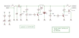
I divide the entire charge controller circuit in to 6 sections for better understanding
1.Voltage sensing
2. PWM signal generation
3. MOSFET switching and driver
4.Filter and protection
5. Display and Indication
6. LOAD On/OFF
Step 3: Voltage Sensors
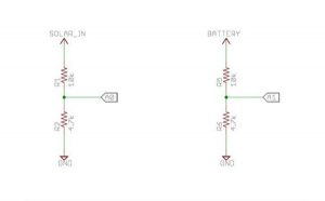
The main sensors in the charge controller is voltage sensors which can easily implemented by using a voltage divider circuit.We have to sense voltage coming from solar panel and the battery voltage.
As the ARDUINO analog pin input voltage is restricted to 5V, I designed the voltage divider in such a way that the output voltage from it should be less than 5V.I used a 5W (Voc=10v)solar panel and a 6v and5.5Ah SLA battery for storing the power .So I have to step down both the voltage to lower than 5V.I used R1=10k and R2 =4.7K in sensing both the voltages(solar panel voltage and battery voltage). The value of R1 and R2 can be lower one but the problem is that when resistance is low higher current flow through it as a result large amount of power (P = I^2R) dissipated in the form of heat. So different resistance value can be chosen but care should be taken to minimize the power loss across the resistance.
I have designed this charge controller for my requirement(6V battery and 5w,6V solar panel),for higher voltage you have to change the divider resistors value.For choosing the right resistors you can also use a online calculator
In code I have named the variable “solar_volt ” for voltage from the solar panel and “bat_volt “for battery voltage.
Vout=R2/(R1+R2)*V
let panel voltage = 9V during bright sunlight
R1=10k and R2=4.7 k
solar_volt =4.7/(10+4.7)*9.0=2.877v
let the battery voltage is 7V
bat_volt = 4.7/(10+4.7)*7.0=2.238v
Both the voltages from voltage dividers are lower than 5v and suitable for ARDUINO analog pin
ADC Calibration :
lets take a example :
actual volt/divider output= 3.127
2.43 V is eqv to 520 ADC
1 is eqv to .004673V
Use this method to calibrate the sensor.
ARDUINO CODE :
for(int i=0;i<150;i++)
{ sample1+=analogRead(A0); //read the input voltage from solar panel
sample2+=analogRead(A1); // read the battery voltage
delay(2);
}
sample1=sample1/150;
sample2=sample2/150;
solar_volt=(sample1*4.673* 3.127)/1000;
bat_volt=(sample2*4.673* 3.127)/1000;
For ADC calibration refer my previous instructables where I have explained in depth .
Step 4: Pwm Signal Generation :
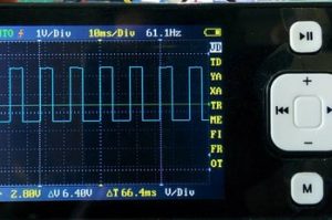
PWM (pulse width modulation) is a tecnique by which we simply control a digital output signal by switching it on and off very quickly, by varying the width of the on/off duration, it will give the effect of varying the output voltage.
Vout = Ton/(Ton+Toff)*Vin
Time period (T)=Ton+Toff
So Vout=Ton/T*Vin
Where Ton/(Ton+Toff) *100 or Ton /T *100 is called Duty Cycle
See the above examples graph (I have taken from Arduino website) for better understanding.
PWM enables a digital output to provide a range of different power levels, similar to that of an analog output.
The best example is fading a LED with different light intensity.This can be done by arduino, using the analogWrite() function.
As Analog output pin is 8bit we can get maximum 2^8=256 or a range of values between 0 to 255.
Sending the value 255, to the LED input produces 100% duty-cycle, which results in full power on a PWM pin.
Sending the minimum value 0, to the LED input produces 0% duty-cycle, which results in no power on a PWM pin.
In Arduino there are 6 PWM pins (3,5,6,9,10 and 11)
I used pin 6 (timer 0) for generating the PWM signal. Arduino Clock has maximum frequency of 16MHz,this can be reduce by using the prescaler. By default Arduino PWM pin have prescaler = 64.
So in pin -6 ,I will get a PWM of frequency 976.5625 Hz by default.But this frequency is quite high for battery charging.So I decided to reduce this frequency to a lower one( 61.035Hz ) by choosing the prescaler value 1024.
Note : I used this frequency because I found that maximum PWM charge controller available in the market have frequency 25/50/100Hz. I don’t have much expertise in this field.If any one have good expertise in battery charging ,please comments about the right frequency selection for PWM .So that I will modify my code.
How to change the Arduino PWM frequncy :
You can adjust the PWM frequency by changing a register value.The register associated with this is TCCR0B.
By selecting three Clock Select Bits of TCCR0B register we can set the proper prescaler.
Are you thinking it is difficult ? No its very very simple just place the single line code given bellow in your program’s void setup() part.Everything is done.I check this by testing the fade example code given in Arduino IDE,it will generate 61Hz.
TCCR0B = TCCR0B & 0b11111000 | 0x05 ; // prescaling 1024
For more details to set the PWM frequency click here
Step 5: How to Choose MOSFETs:
In my charge controller I used two MOSFETs one is for controlling the power flow from solar panel to battery and other is to drive the load.When I started working with MOSFET ,little bit confused how to select a right one.After reading so many forum I found that it is so easy.I think any one can choose the MOSFET by using few guidelines.These are the few important parameters which you will need during choosing a right MOSFET.
Note :
I designed the charge controller as per my requirement ,you have to choose the MOSFETs according to your system requirement.The charge controller rating is mostly depends on MOSFET rating.So choose carefully.
1. N or p channel :
when a MOSFET is connected to ground and the load is connected to supply voltage, it is considered to be a low-side switch. In a low-side switch, an n-channel device is used.In my charge controller I used IRF 540 for driving the load.
A high-side switch is used when the MOSFET is connected to the supply voltage and the load is connected to ground. A p-channel MOSFET is usually used in this topology .I used IRF 9530 as the main switching MOSFET for PWM.
See the schematics how load is connected in both the cases.
2. Drain Source Voltage Vds :
When the MOSFET is turned off, the whole supply voltage will be measurable across it, so this rating should be larger than your supply voltage to provide sufficient protection so that the MOSFET does not fail. The maximum voltage a MOSFET can handle varies with temperature.
3.Continuous Drain Current Ids :
This is the amount of current the MOSFET can handle.You need to simply select the device that can handle the maximum amount of current including surges or “peaks”.Current rating also decreases with rise in temperature.
So keep sufficient margin in Ids.It is better to take current rating @ 125deg Cel.
4. RDS(on) :
When a MOSFET is “on,” it acts as a variable resistor determined by the RDS(on) that changes with temperature with a power dissipation calculated by Iload2 x RDS(on). So choose a MOSFET with smaller value of RDS(on).
5. Thermal Loss:
It can be found from datasheets : the maximum junction temperature and the thermal resistance from junction-to-ambient for the package. The device’s junction temperature is equal to the maximum ambient temperature plus the product of the thermal resistance and the power dissipation (Junction Temperature = Maximum Ambient Temperature + (Thermal Resistance x Power Dissipation) ).
6. Gate Threshold Voltage VGS(th) :
This is the minimum voltage required between the gate and source terminals to turn the MOSFET on. It will need more than this to turn it fully on.
7. Switching Loss :
Charging and discharging the gate capacitance(Cgs) contributes to the switching losses. This loss also depends on the switching frequency.Losses increased with higher switching frequency and gate to source capacitance.
Apart from this , there are several other parameters you have to consider for a good design.For us I think it is sufficient.
For more details on how to choose a right MOSFET click here
Power MOSFET has limitations operation in terms of voltage, current and power dissipation. The power MOSFET current rating is related with the heat dissipated in the devices. This rating will be take in consideration for designing appropriate circuit to protect power MOSFET against high voltage and current, thus cause heat generation.
I used a p-channel MOSFET (IRF9530) for switching between solar panel and battery and a n-channel MOSFET (IRF540) for load.
For higher rated system you have to choose the MOSFET accordingly.
Step 6: MOSFET Drivers
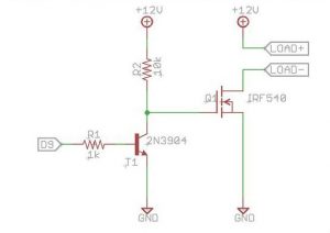
What is a MOSFET driver :
A gate driver is a power amplifier that accepts a low-power input from a micro controller and produces a high-current drive input for the gate of a high-power MOSFET.
why you need a MOSFET driver :
MOSFETs have a large stray capacitance between the gate and the other terminals,which must be charged or discharged each time the MOSFET is switched on or off. As a transistor requires a particular gate voltage in order to switch on, the gate capacitor must be charged to at least the required gate voltage for the transistor to be switched on. Similarly, to switch the transistor off, this charge must be dissipated, i.e. the gate capacitor must be discharged.
When a transistor is switched on or off, it does not immediately switch from a non-conducting to a conducting state; and may transiently support both a high voltage and conduct a high current. Consequently, when gate current is applied to a transistor to cause it to switch, a certain amount of heat is generated which can, in some cases, be enough to destroy the transistor. Therefore, it is necessary to keep the switching time as short as possible, so as to minimize switching loss
Therefore the circuit that drives the gate terminal should be capable of supplying a reasonable current so the stray capacitance can be charged up as quickly as possible. The best way to do this is to use a dedicated MOSFET driver .
There are dedicated chip available in the market for MOSFET driving but it is costly.I used a simple MOSFET driver by using a NPN general purpose transistor.I used 2N3904 but you can use any general purpose transistors like 2N2222 or BC547 etc.
Step 7: Filter and Protection :
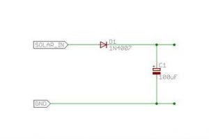
Filter :
The capacitor(C1) used after the solar panel at the input side is used as filter which removes any unwanted ripple/noise signal.
I used a 100uF, 35V.
Optional :
You can also put a capacitor in the load side also.For a better voltage sensor you can use a 0.1uF ceramic capacitor across the R2 and R6.
Protection :
Protections are provided in the charge controller to protect against extreme and abnormal operating condition.
In commercial charge controller there are so many protection.But in my charge controller all are not included.
Following protection are used :
Over Voltage Protection:
During lightening and thundering over voltage occurs in the system.To protect the system a zener diode is used.
I used a 11V zener diode as my solar panel open circuit voltage is 10v. When the voltage is more than 11v ,it will provide the ground path to the surges.
Protection to over current :
Two fuses F1 and F2 are used for over current protection.One is at the incoming side i.e after the solar panel and other is before the load. I forgot to show in the first schematics.
Refer my updated schematics where I put the fuses.
PV panel reverse current :
During night battery voltage is higher in compare to solar panel voltage(0 V).So power can be flow in the reverse direction .This avoided by using a diode(D1) after the solar panel.
Auto Load Disconnection :
To avoid deep discharging of battery ,auto load disconnection scheme is implemented through the software.When the battery voltage is falls below a certain voltage (6.2V)load is automatically disconnected.
Overcharge protection :
Over charge protection is given to improve the battery life and prevent from overheating .When the battery voltage is greater than the fully charged voltage(7.2v) ,it is disconnected from the solar panel to avoid further charging.This is also implemented through the software.
Step 8: Display and Indication
System status display on LCD:
A 16X2 char LCD is used for monitoring solar panel voltage and battery voltage.It also show the % of charge.
When the battery condition is dead it will display :”BATTERY IS DEAD!!” and when battery is discharged it will display “BAT DISCHARGED..”
LED indication on system condition :
2 LEDS (RED,GREEN) are used for indicating the system condition RED LED will glow when battery is discharged
( < 6.2 V) GREEN LED will glow when fully charged (> =7.2 V) and will blink during charging.
When battery voltage is less than 6.2V but greater than 6V RED LED will glow indicating battery is discharged and GREEN LED will blink indicating battery is charging.
LCD -> Arduino
1. VSS -> Arduino GND
2. VDD -> Arduino +5v
3. VO -> Arduino GND pin + Resistor or Potentiometer
4. RS -> Arduino pin 12
5. RW -> Arduino pin 11
6. E -> Arduino pin 10
7. D0 -> Arduino – Not Connected
8. D1 -> Arduino – Not Connected
9. D2 -> Arduino – Not Connected
10. D3 -> Arduino – Not Connected
11. D4 -> Arduino pin 5
12. D5 -> Arduino pin 4
13. D6 -> Arduino pin 3
14. D7 -> Arduino pin 2
15. A -> Arduino Pin 13 + Resistor (Backlight power)
16. K -> Arduino GND (Backlight ground)
If you need more information about LCD interfacing click here
Step 9: How the Charge Controller Works :
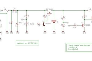
Lets starts to understand the schematics given above:
Power is coming from the solar panel through the diode(D1). A zener diode (D2) is placed at the input terminal to suppress the over voltage. Capacitor C1 is used to remove any unwanted noise/spikes.Then the voltage divider(R1 and R2) is used to sense the solar panel voltage.The out put from the voltage divider goes to Arduino analog pin A0.
The power coming from the solar panel can’t goes directly to battery until the Mosfet(Q1) is On.The switching of the mosfet is done by a PWM signal from Arduino pin-6.Transistor T1 and associated resistance R4 is used for driving the Mosfet(Q1).The resistor R3 is used as a pull up resistor for gate.When the Mosfet is On power goes to battery and charging process starts.
The second voltage divider circuit (R5 and R6) is used for sensing the battery voltage.The output of voltage divider goes to Arduino analog pin A1.
The second Mosfet Q2 is used to drive the load and second transistor T2 is used for driving the Mosfet. During night load will automatically turned on by turning the MosfetQ2 on and will removed when battery voltage is low or day time.
Fuses F1 and F2 are used for over current protection.
LED1(RED) and LED2(GREEN) are hooked to digital pin 7 and 8 of the Arduino for indication.The resistor R7 and R8 are used for limiting the current goes to LEDs.
If you want to use a relay instead of MOSFET Q2 you can.The schematics -2 is given for relay connection.
How Software Works :
At first the charge controller will check the solar panel voltage and compare it with battery voltage ,If it is greater then the Arduino will starts sending pulse width modulation(PWM) signals to the mosfet(Q1) in order to charge the battery .When the solar panel voltage was below the battery voltage ,this pwm signals will not send by Arduino .
Then next the micro controller will check the battery voltage ,if the battery voltage was below 6.96 v volts then the battery will be charged in boost mode ,that mean the battery will be charged with maximum amperage ,this boost mode of charging will be done by sending pulse width modulation signals with 95% duty cycle .
when the battery voltage reaches above 6.96V the charging mode will turn as absorption mode from boost mode ,this was done by changing the duty cycle from 95 % to 10%.This absorption mode will keep the battery fully charged.
A pulse will be send to the load mosfet(Q2) to enable the load during night ,if the battery was too low and reaches to 6.2v volts then in order to prevent deep discharge of the battery ,the load will disconnected.
The arduino code can be Download from my GitHub Account
ARDUINO-SOLAR-CHARGE-CONTROLLER-V-1
Step 10: Solder the Circuit
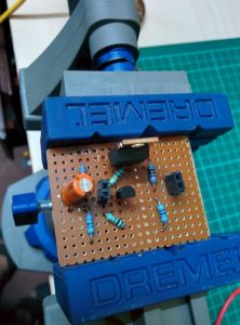
After testing the circuit on a bread board,solder everything on a perforated board.
* clean the copper part of board
* place the components suitably
* Hold it by using a vice
* solder one by one as per schematics
* trim the long legs of all components
* solder 6 wires for terminal connections.(2 for solar panel input,2 for battery and 2 for load)
Step 11: Make the Final Product (CHARGE CONTROLLER)
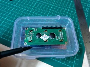
After making the controller on a perforated board place everything in a project box.I did not have any project box,so used a plastic box found in my kitchen.
1 . Mark the size of LCD by a marker or pencil
2. Cut it by a hobby knife. I used my leatherman ES4 which was given by Instructables.
3. Make 2 holes by a drill just below the LCD for inserting 2 LEDS.I used my DREMEL 3000 for drilling.
4 . Hold the 6 pin connector and mark the screw holes ,drill on the marked portion.
5.Drill a big hole for mounting the fuse.solder two wires for connection with the controller.
6. Drill few holes on the side wall of the project box for ventilation.
7. Place the LCD,LEDs, and connector in their place. Then glue it by a hot glue gun.I used my DREMEL glue gun.
8. Put the ARDUINO and Controller inside the box side by side.
9. Put a 9V battery just side to the Arduino for powering it.I used SCOTCH mounting squares for holding.
10.Connect the jumper wires appropriately and test it
Note : put heat shrink or any other insulation tap at all the bare conductors.
Congratulation !!! now the charge controller is ready for charging the battery.
I request viewers to give suggestion for improvement.If you find any mistake please raise it in comment section so that I will rectify it.Any one can modify my code,but please send a copy to me also.
I have described the two major part of the off grid solar system(energy meter,charge controller),only one thing left i.e inverter part.In future if possible I will write on it.just follow me for further updates.

