Summary of Mini Pong arcade using Arduino
Duinocade is a tiny 14 cm arcade cabinet built by hacking an Arcadie Dual gamedock and using Gamebuino/Arduino-based hardware (Nokia 5110 LCD and ATMEGA328). Electronics are assembled on a breadboard (no battery or USB); powered by an external wall supply and fitting into the iPhone slot with one drilled hole for the power jack. The project uses common components and simple tools; future plans include a PCB or DIY kit. The guide covers tools, parts list, enclosure disassembly, sticker removal, and drilling a 7 mm rear cover hole.
Parts used in the Duinocade:
- Arcadie Dual gamedock
- Breadboard 160 x 100 mm
- ATMEL ATMEGA328 microcontroller
- 16MHz crystal
- 2x 15pF disc capacitor
- 2x 100nF disc capacitor
- 220uF/25V electrolytic capacitor
- 10uF/10V electrolytic capacitor
- 10K resistor
- 470 Ohm resistor
- BC547C transistor
- Nokia 5110 LCD
- Loudspeaker > 50 Ohm
- Push button for THT mounting
- MCP1702-3302E/TO (3.3V regulator)
- 2x3 pole header
- 8 pole ribbon cable and header
- Tin-solder
- Hookup wire
- Double-sided adhesive tape
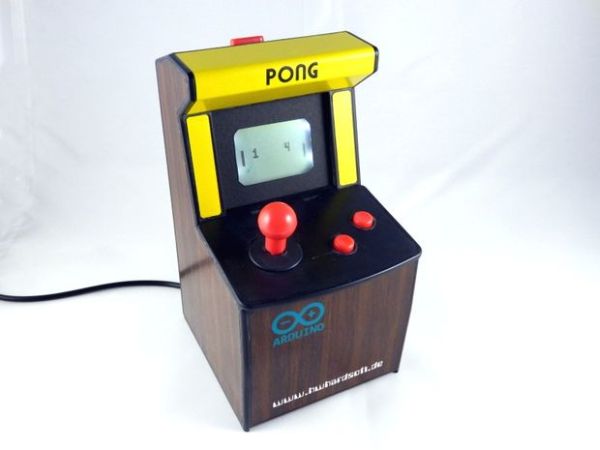
Duinocade is a very small arcade cabinet (14cm / 5,5inch height).
The software and parts of the circuit diagram based on the open source handheld Gamebunio, which based on the famous Arduino platform. The Gamebuino and also our Duinocade uses the known Nokia 5110 lcd as screen. At the moment the Gamedunio is an Indiegogo campain and will be official available in July. But some games for example Pong are finished by the Gamebunio community until now….
I’ve hacked not only the Gamebuino but also an Arcadie Dual gamedock for the case. It is much smaller as the Arcadie gamedocks of my other projects and also cheaper.
The electronic is realized on a breadboard. In the future we will create a pcb layout and perhaps also a DIY kit. In contrast to the Gamebuino we don’t have a lithium battery and an USB port. The Duinocade is powered by an external (wall) power supply. The electronic fits in the slot for the iPhone. We don’t have to made mechanical modifications of the case except one additional hole for the power socket. We’ve mounted only an 3,3V power supply, the ATMEGA328 microcontroller, SD card socket and the Nokia LCD on this breadboard.
Please visit my website for more information.
Step 1: Tools & materials
Tools:
- soldering iron
- electronic side cutter
- flat nose pliers
- simple drilling machine
Materials:
- 1x Arcadie Dual gamedock
- 1x breadboard 160 x 100 mm
- 1x ATMEL ATMEGA328 microcontroller
- 1x 16MHz crystal
- 2x 15pF disc capacitor
- 2x 100nF disc capacitor
- 1x 220uF/25V electrolytic capacitor
- 1x 10uF/10V electrolytic capacitor
- 1x 10K resistor
- 1x 470 Ohm resistor
- 1x BC547C transistor
- 1x Nokia5110 lcd
- 1x Loudspeaker > 50 Ohm
- 1x push button for THT mounting
- 1x MCP1702-3302E/TO
- 1x 2×3 pole header
- 1x 8 pole ribbon cable & header
- tin-solder
- hookup wire
- double-sided adhesive tape
Step 2: Disassemble the Arcadie enclosure
- Remove the both screws (behinde the stickers) at the right and left side of the enclosure
- Cut the cable between joystick unit and rear cover
- Remove the rear cover
- Remove the joystick unit
- Open the rear cover
- Remove all electronic and mechanical parts inside the rear cover
- drill an 7mm hole to the rear cover
Step 3: Remove all the stickers outside
remove the stickers outside the main enclosure, of the backside from rear cover and from the joystick unit. I’m using a label removing spray based on citric acid.
For more detail: Mini Pong arcade using Arduino
- What is Duinocade?
A very small 14 cm arcade cabinet hacked from an Arcadie Dual gamedock using Gamebuino/Arduino-based hardware and a Nokia 5110 LCD. - What powers the Duinocade?
An external wall power supply; there is no lithium battery or USB port. - Which microcontroller is used in the Duinocade?
The ATMEL ATMEGA328 microcontroller is used. - Where is the electronics assembled?
The electronics are realized on a breadboard sized 160 x 100 mm. - Do I need to modify the Arcadie case?
Only one additional 7 mm hole is drilled in the rear cover for the power socket; no other mechanical modifications are required. - Which display does Duinocade use?
The known Nokia 5110 LCD is used as the screen. - Are there plans for a PCB or kit?
Yes, in the future a PCB layout and perhaps a DIY kit are planned. - What tools are required to build Duinocade?
Soldering iron, electronic side cutter, flat nose pliers, and a simple drilling machine are listed. - Which audio component is used?
A loudspeaker with resistance greater than 50 Ohm is used. - How are stickers removed from the enclosure?
Stickers are removed using a label removing spray based on citric acid, then cleaned off the enclosure and rear cover.