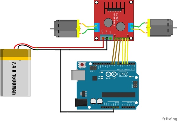
This sketch is used by Exercise: DRV8833 Dual DC Motor Driver.
Full Source Code
The full code is all in one file WheelDrive.ino.
// WheelDrive - move a pair of DC motors at varying rate and direction
//
// Copyright (c) 2016, Garth Zeglin.  All rights reserved. Licensed under the
// terms of the BSD 3-clause license as included in LICENSE.
//
// This program assumes that:
//
//  1. A DRV8833 dual DC motor driver module is connected to pins 5, 6, 9, and 10.
//  2. A pair of motors is attached to the driver.
//  3. The serial console on the Arduino IDE is set to 9600 baud communications speed.

// ================================================================================
// Define constant values and global variables.

// Define the pin numbers on which the outputs are generated.
#define MOT_A1_PIN 5
#define MOT_A2_PIN 6
#define MOT_B1_PIN 10
#define MOT_B2_PIN 9

// ================================================================================
/// Configure the hardware once after booting up.  This runs once after pressing
//// reset or powering up the board.
void setup(void)
{
  // Initialize the stepper driver control pins to output drive mode.
  pinMode(MOT_A1_PIN, OUTPUT);
  pinMode(MOT_A2_PIN, OUTPUT);
  pinMode(MOT_B1_PIN, OUTPUT);
  pinMode(MOT_B2_PIN, OUTPUT);

  // Start with drivers off, motors coasting.
  digitalWrite(MOT_A1_PIN, LOW);
  digitalWrite(MOT_A2_PIN, LOW);
  digitalWrite(MOT_B1_PIN, LOW);
  digitalWrite(MOT_B2_PIN, LOW);

  // Initialize the serial UART at 9600 bits per second.
  Serial.begin(9600);
}

// ================================================================================
/// Set the current on a motor channel using PWM and directional logic.
/// Changing the current will affect the motor speed, but please note this is
/// not a calibrated speed control.  This function will configure the pin output
/// state and return.
///
/// \param pwm		PWM duty cycle ranging from -255 full reverse to 255 full forward
/// \param IN1_PIN	pin number xIN1 for the given channel
/// \param IN2_PIN	pin number xIN2 for the given channel

void set_motor_pwm(int pwm, int IN1_PIN, int IN2_PIN)
{
  if (pwm < 0) {  // reverse speeds
    analogWrite(IN1_PIN, -pwm);
    digitalWrite(IN2_PIN, LOW);

  } else { // stop or forward
    digitalWrite(IN1_PIN, LOW);
    analogWrite(IN2_PIN, pwm);
  }
}
// ================================================================================
/// Set the current on both motors.
///
/// \param pwm_A	motor A PWM, -255 to 255
/// \param pwm_B	motor B PWM, -255 to 255

void set_motor_currents(int pwm_A, int pwm_B)
{
  set_motor_pwm(pwm_A, MOT_A1_PIN, MOT_A2_PIN);
  set_motor_pwm(pwm_B, MOT_B1_PIN, MOT_B2_PIN);

  // Print a status message to the console.
  Serial.print("Set motor A PWM = ");
  Serial.print(pwm_A);
  Serial.print(" motor B PWM = ");
  Serial.println(pwm_B);
}

// ================================================================================
/// Simple primitive for the motion sequence to set a speed and wait for an interval.
///
/// \param pwm_A	motor A PWM, -255 to 255
/// \param pwm_B	motor B PWM, -255 to 255
/// \param duration	delay in milliseconds
void spin_and_wait(int pwm_A, int pwm_B, int duration)
{
  set_motor_currents(pwm_A, pwm_B);
  delay(duration);
}

// ================================================================================
/// Run one iteration of the main event loop.  The Arduino system will call this
/// function over and over forever.
void loop(void)
{
  // Generate a fixed motion sequence to demonstrate the motor modes.

  // Ramp speed up.
  for (int i = 0; i < 11; i++) {
    spin_and_wait(25*i, 25*i, 500);
  }
  // Full speed forward.
  spin_and_wait(255,255,2000);

  // Ramp speed into full reverse.
  for (int i = 0; i < 21 ; i++) {
    spin_and_wait(255 - 25*i, 255 - 25*i, 500);
  }

  // Full speed reverse.
  spin_and_wait(-255,-255,2000);

  // Stop.
  spin_and_wait(0,0,2000);

  // Full speed, forward, turn, reverse, and turn for a two-wheeled base.
  spin_and_wait(255, 255, 2000);
  spin_and_wait(0, 0, 1000);
  spin_and_wait(-255, 255, 2000);
  spin_and_wait(0, 0, 1000);
  spin_and_wait(-255, -255, 2000);
  spin_and_wait(0, 0, 1000);
  spin_and_wait(255, -255, 2000);
  spin_and_wait(0, 0, 1000);

  // and repeat
}
/****************************************************************/
Source: Arduino Sketch Wheel Drive