Hello Everyone, thank you for showing interest in our project. In this project, we are showing a fully automated robot that sorts fruits and vegetables based on their color.
The project happened in the context of the Bruface program and more precisely in the mechatronics 1 course. The Brussels Faculty of Engineering (in short, Bruface) is a joint initiative between Vrije Universiteit Brussel (VUB) and Université Libre de Bruxelles (ULB), offering a broad spectrum of fully English-taught Master Programmes in the field of Engineering.
The team is composed of 3 members
- Ankit Pandey
- Tigran Pletser
- Julien van Delft
The main purpose of the Mechatronics course is to teach both mechanical structure and electronics. This is the reason why we chose a robot with a mechanical solid structure and a moving flexible gripper able to detect the fruit in a certain zone and sort them by color.
Initially, we started with a silicone molded soft gripper for sorting vegetables/fruit based on its matureness but as the laboratory was closed for November due to coronavirus and very little time was available to create the soft gripper we switched to a flexible gripper instead of a soft gripper by readapting this gripper found on thingyverse : https://www.thingiverse.com/thing:2316823
The project took 3 months to complete but do not worry this project will regroup all the files needed for the building of the vegetable/fruit sorter robot.
The project is about the fabrication of a vegetable/fruit gripper sorter. The gripper is made in a flexible way to be able to pick fragile fruits of various sizes. The total budget you should consider to make this project is around 100-150€ (120-180$) and it will take you 15 to 20h of work to build the entire prototype. We advise you to have someone to help you at some point when you will build the global structure to hold the plate while you screw them together.
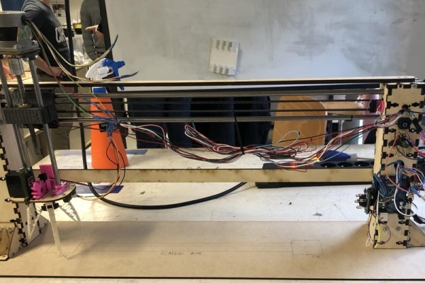
Step 1: Mechanical Design
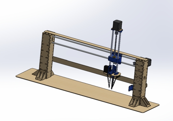
The design looks like this with two laser-cut feet with small supports to ensure stability.
The motion is driven by a belt and a stepper motor fixed to the right feet and a lead screw and a stepper motor fixed on the top.
Two linear rods of 70cm are attached between the two feet on which the gripper will slide thanks to linear bearings.
To ensure a good motion in Z, two linear rods of 22cm are also fixed with the motor and sliding in linear bearings in the fixation.
The gripper in itself is driven by a 3D-printed rack and pinion and a servo motor controlling the opening and the closing of the gripper. It is a flexible gripper allowing it to take various sizes of objects.
Needed Material
All the needed material is in the list below.
- tons of screws and bolts M3 (for the laser cut assembly mainly) and M5
- 2 Linear rods 8mm diameter 70cm long
- 2 Linear rods 8mm diameter 22cm long
- 1 Lead screw and trapezoidal nut 8mm diameter 15 cm long
- 1 Trapezoidal belt 5mm width, 1.4m long
- 1 Arduino Uno
- 2 Stepper motor NEMA 17 (needed torque around 20Ncm at least)
- 1 Shaft coupler 5x8mm
- 1 pulley 5mm inside diameter
- 2 Stepper motor drivers DRV8825
- 1 Servomotor MG996R
- 1 Ball bearing 5mm inside diameter, 13mm outside diameter
- 5 Linear bearings 8mm inside diameter,15mm outside diameter
- 1 color sensor TCS3200
- 1 Laser range sensor GP2Y0A21
- 2 end switches SS-5GL
- 1 Potentiometer
- 1 Button
- 1 Voltage source 12V (we chose a 12V PDC004 to power the robot through usb-c)
- 1 DC-DC Voltage step down power module LM2596
- Cables
Needed Prerequisite
To finish this project, you will need some basic electronic knowledge in order to connect everything and most importantly, not burn a component or even worst your laptop. Also, you will need to solder cables and components so either you will need to be good at soldering or good in electronic debugging to find the problem after some soldering errors (trust me it happens very often). Same for the coding, we will give you every codes and files to build the project but bugs may occur, knowing the basics about Arduino coding is good to have.
Tools
Lots of pieces are laser cut or 3D printed so you will need access to both a 3D printer and a laser cutter. If like us, you cannot directly obtain the right size of linear rods and lead screw, a metal handsaw or even better a metal cutting rotating saw will save you some hard physical effort to cut your pieces. For the rest, you will need some basic tools as screwdrivers, measuring tools such as caliper, hammer, and so on. To solder components and the wires, a soldering iron is needed as well as tin. Finally, for the 3D printer and the laser cutter, we use regular PLA and birch plate of 3mm and 6mm thickness.
Step 2: 3D Printing
As a 3D printer is a slow and capricious machine, it is better to start making the 3D printed pieces.
The pieces we printed are made of regular PLA but you can use whatever you want. Be sure that you adapt the settings (especially the bed and nozzle temperature) to have good prints. Normally, the right temperature is always written on the spool. For the slicing software, we used Cura which is a good user-friendly software nice if you never used a 3D printer.
Some pieces need support while printing. Be careful of setting the support in your slicer to have good printing. In the following list, you will find the name of all pieces needed:
- Linear rod fixation: 7 pieces (without support)
- Rack: 1 piece (with support)
- Colour sensor holder: 1 piece (without support)
- Finger holder : 3 pieces (without support)
- Flexible finger : 3 pieces (without support)
- Linear rod fixation 2: 1 piece (without support)
- Rack guide: 1 piece (without support)
- Servo holder: 1 piece (without support)
- Servo holder 2: 1 piece (without support)
- Servo motor pinion: 1 piece (without support)
- Zero: 1 piece (without support)
- Belt tensioner: 2 pieces (without support)
- Switch holder: 1 piece (without support)
- YZ junction: 1 piece (with support)
- Potentiometer holder (with support)
- Potentiometer Knob (without support)
- Button case (without support)
Pay attention to choose the right orientation when slicing the stl. Indeed, a piece without support in a direction can need some in another one.
All the pieces were printed with 20% of infill in order to be solid enough.
Now while your 3D printer is working for approximately 20 years, you can continue with the laser cutting parts.
Step 3: Laser Cutting
The laser cutter is a quick and wonderful way to create 3D shapes with a wood plate.
To make the pieces you will need Birch 3mm and Birch 6mm thickness plate. The pieces are listed below together with the thickness needed.
Birch 3mm
- 1x Z bottom
- 1x Z top
- 6x Support back
- 6x Supportbottom
- 12x Support middle
- 6x Support sides
Birch 6mm
Motor foot
- 1x Front side BIG
- 1x Motor side BIG
- 1x Rod side BIG
- 1x Side side BIG
- 1x Top side BIG
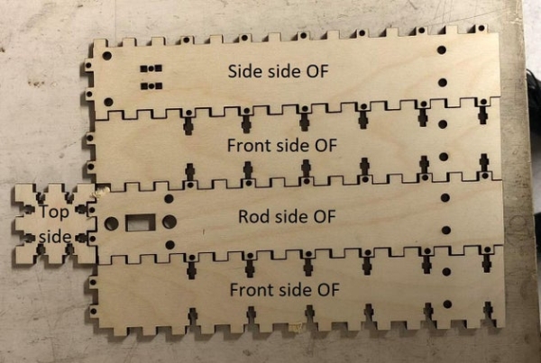
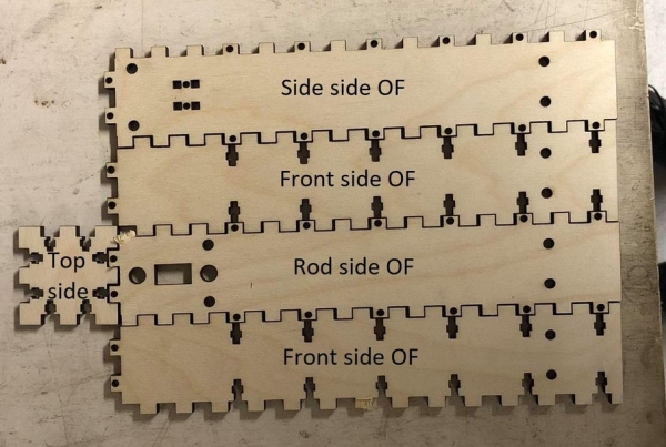
Other foot
- 2x Front side OF BIG
- 1x Rode side OF BIG
- 1x Side side OF BIG
- 1x Top side BIG
Big stands for big thickness as we cut it in thick birch plate of 6mm and OF for other feet as opposed to the motor feet in which the motor is fixed.
Solidification
The solidification is not mandatory for the final assembly but better to have stability and avoid twisting as the linear rods are very long.
- 2x TopSupport
- 1x Plate of at least 90cmx20cm
The parameters for your laser cutter may vary but we advise you to cut the 3mm at 90% power and 18mm/s and the 6mm at 90% power and 10mm/s.
Step 4: Assembly
The assembly will take you most of the time. To build the mechanical structure, you need to follow those steps (the pictures will help you to see how to put the pieces together):
Structure
- Assemble all the support by attaching the support bottom to two support middle using M3 screws with bolts. Then, put the support side in the middle and fix the support back to the rest with M3 screws again and putting the bolts in the space provided. Repeat this step for the 6 supports.
- Attach the 6 supports to each face except the Rod side BIG and Rod side OF BIG.
- Insert the linear rods into one linear rod fixation each so that you still have free access on one side. You can use a hammer for the insertion and hit the top of the linear rod to have a good fixation.
- Insert an M4 screw in one belt tensioner, add a nut and the bearing and finally the other belt tensioner and the last nut to fix everything together.
- Put the belt tensioner in the squared holes in the Side side OF BIG and screw it with a bolt in the notch provided in the belt tensioner. Just fix it without screwing it because you will need to adapt the screwing to tension the belt.
- Fix the NEMA 17 stepper motor in the Motor side BIG with 4 M3 screws and add the pulley at the end of the shaft. Same for the colour sensor in the colour sensor holder and then attach it to the Rod side BIG. If you have M2 screws, fix the limit switches in the switch holder and in the YZ junction (in the two small holes on the bottom). If you do not have M2 screws, you can just glue them in the right position. Finally, screw the limit switch holder in the Rode side BIG. Beware that the limit switch should be on the right of the Rod side BIG holes.
- If you want to attach the Arduino to the foot, they are some holes in the Front side BIG that are made for it. But it may be better to first do all the electronics and fix it afterwards. Same for the potentiometer, you can fix on in the same face (just above the lines) with the potentiometer holder and M3 screws.
- Put the linear bearings in the YZ junction, 2 for the Z direction and 3 for the Y direction and fix the lead screw nut (with the head down) in the middle hole of the YZ junction with M3 screws.
- Now, complicated task incoming. Fix the 70cm linear rods in the Side side BIG with the linear rod fixation and M5 bolts. Then, make the Rod side BIG slide on the linear rods through the holes provided. After that, make the YZ junction and Rod side OF BIG follow the same path.
- Finally, attach the two missing linear rod fixations to the end of the linear rods and let the bottom one exceed of 5cm. Fix the fixations into the Rod side OF BIG for the bottom one and in the Side side OF BIG for the top one.
- Take the belt and put it around the bearing and make it pass through the rectangle hole in the Rod side OF BIG.
- Now you can fully assemble the left foot, attach the two Front side OF BIG in the Side side OF BIG with the finger joints and screw them with M3 bolts. And fix the Top side BIG using the same method.
- Same for the foot with the motor. Although, you have to be careful to put the belt around the pulley while fixing the Motor side BIG.
- Fix the belt in the YZ junction by passing it in the small fixations provided on the back between the two linear rods, making a loop in each of them and zipping the belt on itself.
- Adjust the tension of the belt by screwing more or less the screws of the belt tensioner‘s
Z axis
- Attach the NEMA 17 in the Z top with M3 screws. Put the shaft coupler on the motor shaft and attach the lead screw on the other side.
- Fix the linear rods 22cm long in the Z top with the linear rod fixation previously attached with M5 bolts.
- Fix the servo motor pinion in the servomotor with the small screws given with it and then fix the servomotor to the Z bottom with the Servo holder on one side and the servo holder 2 on the other.
- Attach the Rack guide, the Zero with M3 screws and put the Rack in the space provided. Finally, attach the Sharp sensor and finger holders on the bottom side of the Z bottom with M3 screws and bolts.
- Link the centre holes of the fingers together. Attach the finger end holes, one in the finger holder and the other in the Rack‘sbottom. As the holes are really small, you can use cables to fix them.
- Make the linear rods slide into the YZ junction linear bearings previously inserted and make the lead screw rotate in the fixed nut to make the motor go down.
- Finally, insert the linear rods into one linear rod fixation for the right one (motor foot side) and the other in the linear rod fixation 2 (that has a V-shape). Fix them to the Z bottom using M5 screws and bolts.
Solidification
If you want to make the structure more solid and avoid some twisting, you can fix the TopSupport on the top of the two feet with small screws and also one on the back (as shown on the picture). To have a good rigid structure, you can fix it to a plate with the holes in the small feet supports and screws.
You have now completed the assembly of the robot. If you arrived at this step without throwing everything through the window, congratulations. Don’t worry, it is almost finished.
Step 5: Electronics Design
Electronic List :
- 2 Bipolar stepper motor (NEMA17)
- 2 Stepper driver (DRV8825)
- 1 USB-C 12V supply (PDC004) (or any 12V power supply)
- 1 Step down converter (12V -> 5V)
- 1 Arduino Uno
- 1 range sensor (GP2Y0A21)
- 1 color sensor (TCS3200)
- 1 servo motor ()
- 2 limit switches
- 1 potentiometer
- 1 button
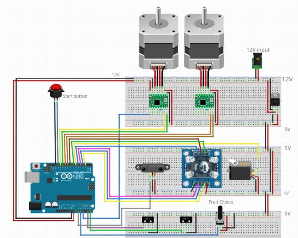
The electronics design consists of 2 different voltage zones linked by the step-down converter.
The first zone is the 12V zone. It is powered by the PDC004 and feeds the stepper drivers and the stepdown converter. The stepper drivers feed the stepper motors and are mounted on 2 custom PCBs which are placed on the Side side BIG. The Arduino is also on the 12V side (plugged in the Vin pin) to assure not to damage anything connected to it.
The second zone is the 5V zone. It is powered by the step-down converter. It feeds the range sensor, the color sensor, the servo motor, the potentiometer, the limit switches, and the button.
The Arduino connections are as follows :
- Colour sensor S0 pin: Digital pin 8
- Colour sensor S1 pin: Digital pin 7
- Colour sensor S2 pin: Digital pin 2
- Colour sensor S3 pin: Digital pin 3
- Colour sensor OUT pin: Digital pin 4
- Colour sensor LED pin: Digital pin 5
- Servo motor signal pin: Digital pin 6
- Z-axis Stepper driver DIR pin: Digital 9
- Z-axis Stepper driver STEP pin: Digital 10
- Y-axis Stepper driver DIR pin: Digital 11
- Y-axis Stepper driver STEP pin: Digital 12
- Start button: Digital pin 13
- Y-axis limit switch: Analog pin A5 (used as a digital pin)
- Z-axis limit switch: Analog pin A4 (used as a digital pin)
- Y-axis Stepper driver ENABLE pin: Analog pin A2 (used as a digital pin)
- Potentiometer signal pin: Analog pin A1
- Range sensor signal pin: Analog pin A0
Source: Fruit Sorter Robot Using Flexible Gripper