
Summary of Arduino Sketch ReadSwitchInput
This article presents an Arduino sketch named "ReadSwitchInput" that reads the state of a digital switch and displays the result via an onboard LED and the serial monitor. The code initializes a switch on pin 2 with a pull-up resistor and configures the built-in LED as an output. It continuously reads the switch value, updates the LED to reflect the state (active-low logic), and prints the data to the console at a baud rate of 9600.
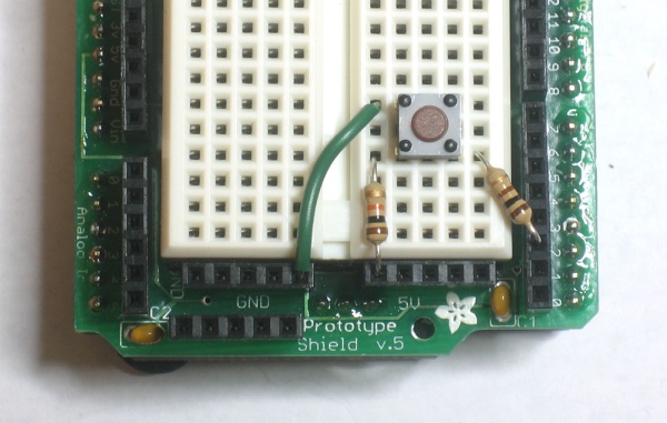
Parts used in ReadSwitchInput:
- Arduino Board
- SPST Switch
- 10K Pullup Resistor
- Digital Pin 2
- Built-in LED (LED_BUILTIN)
- Serial Console/IDE
This sketch is used by Exercise: Read Switch Input.
Full Source Code
The full code is all in one file ReadSwitchInput.ino.
// ReadSwitchInput - read a digital input and report its value using the LED and serial monitor
//
// Copyright (c) 2016, Garth Zeglin.  All rights reserved. Licensed under the
// terms of the BSD 3-clause license as included in LICENSE.
//
// This program assumes that:
//
//  1. An SPST switch connected between digital pin 2 and ground, and a 10K
//  pullup resistor between digital pin 2 and +5V.
//
//  2. The serial console on the Arduino IDE is set to 9600 baud communications speed.
// ================================================================================
// Define constant values.

// The wiring assignment.
#define SWITCH_PIN 2

// ================================================================================
// Configure the hardware once after booting up.  This runs once after pressing
// reset or powering up the board.

void setup()
{
  // Initialize the serial UART at 9600 bits per second.
  Serial.begin(9600);

  // Initialize the hardware digital pin 13 as an output.  The 'OUTPUT' symbol
  // is pre-defined by the Arduino system.
  pinMode(LED_BUILTIN, OUTPUT);

  // Initialize the switch pin for input.
  pinMode(SWITCH_PIN, INPUT);
}

// ================================================================================
// Run one iteration of the main event loop.  The Arduino system will call this
// function over and over forever.
void loop()
{
  // Read the switch value.  As wired, it is 'active-low', so if the switch is
  // open the value will be 1 (HIGH), else 0 (LOW).
  int value = digitalRead(SWITCH_PIN);

  // Output the value to the onboard LED.
  digitalWrite(LED_BUILTIN, value);

  // Print the value out the serial port so it can be seen on the console.  This
  // can take time, so this delay is the primary determinant of the inptu
  // sampling rate.
  Serial.println(value);
}
// ================================================================================
Source: Arduino Sketch ReadSwitchInput
-
What is the primary function of the ReadSwitchInput sketch?
The program reads a digital input and reports its value using the LED and serial monitor. -
How should the SPST switch be wired for this project?
The switch connects between digital pin 2 and ground, with a 10K pullup resistor connecting digital pin 2 to +5V. -
At what baud speed must the serial console be set?
The serial console must be set to 9600 baud communications speed. -
Which pin is initialized as an output for the LED?
Digital pin 13, identified by the constant LED_BUILTIN, is initialized as an output. -
Why does the code use active-low logic for the switch?
Because of the wiring configuration, an open switch results in a value of 1 (HIGH) and a closed switch results in 0 (LOW). -
What determines the input sampling rate in the loop?
The delay caused by printing values to the serial port is the primary determinant of the input sampling rate. -
Where can the full source code for this project be found?
The full code is contained entirely within one file named ReadSwitchInput.ino.
