Summary of Arduino Science Clock
This article details the construction of a unique science-themed clock featuring periodic table elements instead of numbers, offering both analogue and digital time displays. The project utilizes an Arduino Mega, stepper motors for hands, and an LED sequence for digital indication. Designed with Fusion 360 and fabricated using a laser cutter and 3D printer, the clock includes a plywood face, brass axle, and various electronic components to create a functional gift.
Parts used in the Arduino Science Clock:
- 1 x 3mm Plywood sheet (600mm x 400mm)
- 4 x Red 5mm LEDs
- 4 x Blue 5mm LEDs
- 4 x Green 5mm LEDs
- 4 x Yellow 5mm LEDs
- 12 x 220 ohm resistors
- 1 x Roll of Hookup wire
- 1 x PLA filament for 3D Printer
- 1 x 300mm long 8mm diameter Brass Rod
- 4 x 8mm Shaft Collars
- 1 x 8mm Self Aligning Pillow Block Bearing
- 2 x Stepper Motors (28BYJ-48)
- 2 x Driver Board Modules (ULN2003)
- 4 x Spring Return Push Buttons
- 1 x 2 position Toggle Switch
- 1 x Arduino Mega
- 1 x Real Time Clock Module (DS1307)
I have toyed with the idea of building a clock for sometime and my sister had a big birthday coming up so I decided that this was a great opportunity to build a clock for her as a gift. My sister has a PhD in science and works as a science educator so I decided to make a science themed clock.
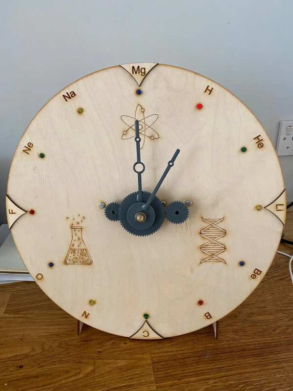
I wanted to make the clock slightly different, the first thing that stands out with this clock is that it doesn’t have numbers, I used the periodic table elements instead. For those of you that don’t know here’s a list of the elements I used with there corresponding number
- H-Hydrogen
- He-Helium
- Li-Lithium
- Be-Beryllium
- B-Boron
- C-Carbon
- N-Nitrogen
- O-Oxygen
- F-Fluorine
- Ne-Neon
- Na-Sodium
- Mg-Magnesium
So rather than 6 O-Clock it is actually carbon o-clock etc.
The clock has both digital and analogue systems for time keeping. The analogue system simply uses two stepper motors for moving the hands in hour or minute steps. The hands can be adjusted manually with the buttons on the side of the electronics enclosure. The digital system keeps track of the time by lighting up an LED adjacent to the corresponding hour. I have also made this part of the clock more interesting, at the turn of the hour the LEDS light up in sequence forward then backwards through the next corresponding 12 hours and then stops at the current hour staying lit for the next 60 minutes. The combination of using Fusion 360 and my 3D printer really made the analogue part of this clock build very easy.
Supplies
The Supplies I used were as follows:
1 x 3mm Plywood sheet, 600mm x 400mm
4 x Red 5mm LEDs
4 x Blue 5mm LEDs
4 x Green 5mm LEDs
4 x Yellow 5mm LEDs
12 x 220 ohm resistors
1 x Roll of Hookup wire
1 x PLA for 3D Printer
1 x 300mm long 8mm diameter Brass Rod
4 x 8mm Shaft Collars
1 x 8mm Self Aligning Pillow Block Bearing
2 x Stepper Motors, 28BYJ-48
2 x Driver Board Modules for Stepper Motors, ULN2003
4 x Spring Return Push Buttons
1 x 2 position Toggle Switch
1 x Arduino Mega
1 x Real Time Clock Module, DS1307
The Tools I used were:
3D Printer
Laser Cutter
Soldering Iron
General Hand Tools
Step 1: Mechanical Design
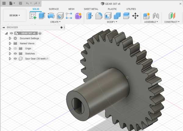
The clock hands and gear mechanism was designed using Fusion 360, the gears were then printed on a 3D printer. I found the combination of using my 3D printer together with Fusion 360 meant I could rapidly prototype many different designs before I got to the final gear train design.
Each hand is driven by a stepper motor through a pair of spur gears, the pinion gear is connected directly to the stepper motor and the driven gear is on the 8mm brass axle. Each gear has a 2:1 reduction, this is to take the torque load of the the stepper motor hopefully increasing the life of the motor. The hour hand has a 25:50 gear ratio and the Minute hand has a 30:60 ratio.
The hour stepper motor turns the axle through the 50 tooth gear. The 50 tooth gear is secured to the axle with a locking collar. The hour hand is the driven by the shaft, also being connected via a locking collar. The minute hand is on the 60 tooth gear which can freewheel around the 8mm shaft, this is driven by the minute stepper motor and the 30 tooth gear.
The spur gears were designed using the Fusion 360 spur gear add in, this functionality being very important for this project. The way I designed the gears was as follows:
- Click the utilities Tab
- Click on the Scripts and Add-ins on the tool bar
- Scroll down to spur gear and select run
- A menu will then a appear to enter your gear parameters
- Click run and your gear will appear on the screen
Once the gear was generated I then added the shaft with the required flats to connect to the motor.
The gears that needed to be coupled to the axle were fitted with a locking collar. I connected the steel locking collar to the gear using 2-part epoxy glue. The 8mm brass shaft was used to make sure the collar was correctly aligned.
Once all of the gears were designed on Fusion 360 the files were exported as an stl file. The stl file was then opened up in Cura and sliced ready for 3D printing. With Fusion 360 there is the option to automatically generate the stl file and send to Cura directly, Fusion 360 also opens Cura with your print ready to slice. The 3D printing was done with a Creality Ender 3 Pro. The small gears took about 20 minutes each to print and the large gears took about an hour to print. The clock hands were also designed on Fusion 360 and 3D printed the same way.
Step 2: Plywood Clock Face and Enclosure
The main clock face, electronics enclosure and supports were manufactured from 3mm plywood. This is a fairly straightforward 2D design so I used a simple 2D CAD package to design the clock face and supports.
I tried to find some pictures of a chemical flask, DNA and an atom on line to download with no luck so they were drawn from scratch.
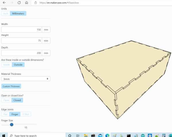
I cheated for the electronics enclosure as I used an online box making tool. I used makercase.com. With this tool you put in all your settings for your enclosure and it then generates a drawing of the box of which you can download dxf and svg files. This tool is awesome for quickly designing boxes!
Once the drawings were done it was time to cut out the parts using a laser cutter. The laser cutter at the hackspace I am a member of uses LightBurn software which seems pretty compatible with most file formats. I find using an engineering CAD package quite useful as I can use different layers for different types of laser cuts, for example the outline can be drawn in a layer for a full cut, the text engraving can then be a different layer with a lower intensity. The LED holes were another layer so the cut sequence could be optimised. The small LED’s are 5mm so the holes were 6mm.
To secure all the plywood elements I just used standard wood glue.
Step 3: Electronics Design
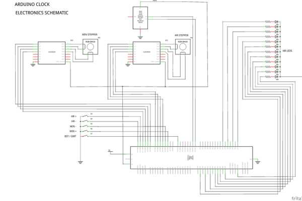
The electronics design is pretty straight forward.
The main input is the DS1307 Real Time Clock Module. This simply needs a power supply and connection to the Arduino via the I2C bus (SDA/SCL).
There are 4 push button inputs for the user to adjust the minute hands forwards and backwards, these are connected via internal pullups on the Arduino and are activated when connected to ground.
There is also a toggle switch which allows the user to switch between UTC and BST. This means during the summer it advances which LED is lit. This button does not effect the hands.
The outputs are the 12 LEDs which light up on the hour and also come on in a sequence defined in the code.
The other outputs are the two 28BYJ-48 Stepper motors and associated driver boards. The Arduino pins connected to the driver boards are specified in the code.
A full schematic drawing is shown in the pictures above.
Step 4: The Code
Together with the gear mechanism the code is at the heart of this project.
I am not going to explain every line of this code, I am just going to detail a few snippets.
Global Variables and Libraries.
#include "RTClib.h"<br>#include <Stepper.h><br><stepper.h></stepper.h>
RTC_DS3231 rtc;
int skip = 0;
const int stepsPerRevolution = 200; //for the motor itself, total steps w/ reduction ~2038
//Stepper clockStepper(stepsPerRevolution, 8, 10, 9, 11);
Stepper clockStepperMin(stepsPerRevolution, 11, 9, 10, 8);
Stepper clockStepperHr(stepsPerRevolution, 7, 5, 6, 4);
int timer = 100;           // The higher the number, the slower the timing.
int ledPins1[] = {31, 33, 35, 37, 39, 41, 43, 45, 47, 49, 46, 53};       // an array of pin numbers to which LEDs are attached
int ledPins2[] = {33, 35, 37, 39, 41, 43, 45, 47, 49, 46, 53, 31};       // an array of pin numbers to which LEDs are attached
int ledPins3[] = {35, 37, 39, 41, 43, 45, 47, 49, 46, 53, 31, 33};       // an array of pin numbers to which LEDs are attached
int ledPins4[] = {37, 39, 41, 43, 45, 47, 49, 46, 53, 31, 33, 35};       // an array of pin numbers to which LEDs are attached
int ledPins5[] = {39, 41, 43, 45, 47, 49, 46, 53, 31, 33, 35, 37};       // an array of pin numbers to which LEDs are attached
int ledPins6[] = {41, 43, 45, 47, 49, 46, 53, 31, 33, 35, 37, 39};       // an array of pin numbers to which LEDs are attached
int ledPins7[] = {43, 45, 47, 49, 46, 53, 31, 33, 35, 37, 39, 41};       // an array of pin numbers to which LEDs are attached
int ledPins8[] = {45, 47, 49, 46, 53, 31, 33, 35, 37, 39, 41, 43};       // an array of pin numbers to which LEDs are attached
int ledPins9[] = {47, 49, 46, 53, 31, 33, 35, 37, 39, 41, 43, 45};       // an array of pin numbers to which LEDs are attached
int ledPins10[] = {49, 46, 53, 31, 33, 35, 37, 39, 41, 43, 45, 47};       // an array of pin numbers to which LEDs are attached
int ledPins11[] = {46, 53, 31, 33, 35, 37, 39, 41, 43, 45, 47, 49};       // an array of pin numbers to which LEDs are attached
int ledPins12[] = {53, 31, 33, 35, 37, 39, 41, 43, 45, 47, 49, 46};       // an array of pin numbers to which LEDs are attached
The above code shows what libraries are used for the Real Time Clock, the Steppers. It defines the name of the steppers, how many steps and the pins used. There are 12 arrays which are used in a custom function for doing the LED flashing sequence on the hour.
The code below is used in the setup function to setup the clock. Basically if the real time clocks seconds value is zero then it advances the minute hand. Because the steps per revolution on the steppers is not divisible by 360 this section of code deals with any error correction. This is the section of code you need to play with to tune the clock if it is fast or slow. In my code every 30 minutes the minute hand advances slightly further on the 30th minute.
if (now.second() == 0) {
skip += 1;
    if (skip != 29) {
      //Serial.print("advance stepper 34 steps"); Serial.print(" skip "); Serial.println(skip);
      clockStepperMin.step(-68); //advance ~1:00
      delay(1000);
    }
    else {
      skip = 0;
      //Serial.print("1 step skipped to keep correct time"); Serial.print(" skip "); Serial.println(skip);
      clockStepperMin.step(-72); //advance ~1:00 minus 1 step to keep clock in time
      delay(1000);
    }
  }
On the hour is when the most complicated part of the sketch happens as it calls a custom function. The snippet below shows what happens at 2 o-clock. The stepper is advanced then the 2 o-clock function is called to do something with the LEDs.
if (now.second() == 4 && now.minute() == 0 && now.hour() == 2) {<br>    //Serial.print("advance stepper 34 steps"); Serial.print(" skip "); Serial.println(skip);
    clockStepperHr.step(342); //advance ~1:00
    delay(1000);
    if (dstButton == LOW) {
      Two_oclock();
    } else {
      Three_oclock();
    }
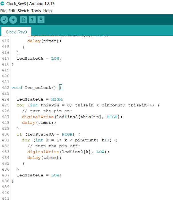
Below is the custom function which is called at 2 o-clock. This sequences the LEDs as defined in the ledPins4 array.
void Two_oclock() {<br>
  ledState0A = HIGH;
  for (int thisPin = 0; thisPin < pinCount; thisPin++) {
    // turn the pin on:
    digitalWrite(ledPins2[thisPin], HIGH);
    delay(timer);
  }
  if (ledState0A = HIGH) {
    for (int k = 1; k < pinCount; k++) {
      // turn the pin off:
      digitalWrite(ledPins2[k], LOW);
      delay(timer);
    }
  }
  ledState0A = LOW;
}
I have attached 2 versions of the code. The first is very long but easy to understand. The second is much shorter but is more advanced as it fully uses the custom functions by passing variables back and forward. The second version was developed by a Hackspace friend, Paul, after he read my original code and was challenged to optimise it.
Step 5: Final Assembly and Testing
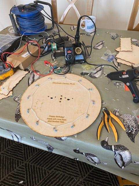
The final assembly and testing was simply a hot mess of solder, wires and hot glue. A great way to spend a rainy Sunday afternoon.
The first thing I did was solder a 220 ohm resistor to the anode (+) of each LED. I then hot glued each LED into the clock. Next I connected all the cathodes (-) to each other in sequence ready to connect to ground. I then connected a long wire to each resistor ready to connect to the corresponding output on the Arduino Mega.
When the LEDs were assembled I assembled the hands drive system including the stepper motors and then threaded all the wires into the electronics enclosure.
Inside the electronics enclosure I connected the RTC (real Time Clock), the 5 input switches, the two Stepper Driver PCB’s, and the LED connections all according to the schematic.
Once assembled I tested it out and it worked pretty well. I found that it looses about 2 minutes a day which can be corrected in the code with some trial and error.
Source: Arduino Science Clock
- How does the clock display time without numbers?
The clock uses periodic table element symbols corresponding to their atomic number instead of traditional numerals. - What software was used to design the gears?
Fusion 360 with the spur gear add-in was used to design and generate the gear parameters. - Can the clock hands be adjusted manually?
Yes, the hands can be adjusted manually using the buttons located on the side of the electronics enclosure. - How does the digital LED system indicate the hour?
At the turn of the hour, LEDs light up in a sequence forward then backward through the next 12 hours before stopping at the current hour. - What is the function of the toggle switch?
The toggle switch allows the user to switch between UTC and BST modes to adjust the lit LED during summer time. - Which motor driver boards are used for the stepper motors?
The project uses two ULN2003 driver board modules for the two 28BYJ-48 stepper motors. - How often does the minute hand advance in the code?
The minute hand advances every minute when the seconds value is zero, with error correction applied every 30 minutes. - What tool was used to cut the plywood parts?
A laser cutter running LightBurn software was used to cut the 3mm plywood clock face and enclosure. - Does the clock lose or gain time over a day?
The author noted the clock loses about 2 minutes a day, which can be corrected via code adjustments. - What real-time clock module is connected to the Arduino?
A DS1307 Real Time Clock Module is used as the main input for timekeeping data.