Summary of Arduino Row-column Scanning to control an 8×8 LED Matrix Code
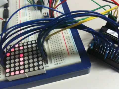
This article explains controlling an 8x8 LED matrix by row-column scanning with an Arduino, using two potentiometers as X-Y inputs to move a lit LED. Rows are tied to positive (anodes) and columns to negative (cathodes); driving appropriate row low and column high lights a specific LED. It lists required pins and components and includes code and schematic references for wiring and pin arrays.
Parts used in the 8x8 LED Matrix Row-Column Scanning Project:
- Arduino board
- 8 x 8 LED matrix (e.g., Lumex LDM-24488NI)
- Potentiometer 1
- Potentiometer 2
- Hook-up wire
- Breadboard
LED displays are commonly packaged as arrays of LEDs organized in rows with shared positive terminals and columns with shared negative terminals, or vice versa. Here is a standard illustration, along with its diagram:
These exhibits can be very useful. To control a matrix, you connect its rows and columns to your microcontroller. The columns are connected to the LEDs’ negative terminals (see Figure 1), so a column needs to be in a high state for any LED in that column to illuminate. The LEDs are linked to the positive terminals of the rows, so a low current in a row is necessary for a single LED to illuminate. If the row and column have matching high or low levels, the LED will not be activated and will stay unlit.
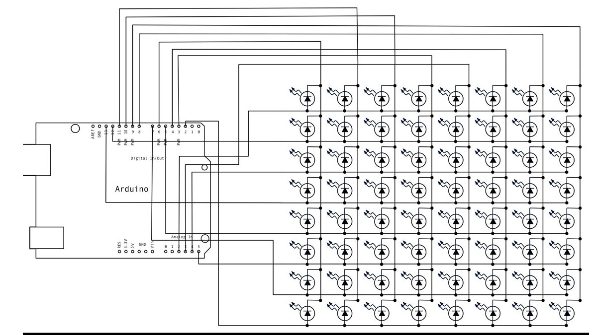
Circuit
The 16 pins of the matrix are hooked up to 16 pins of the Arduino. Four of the analog pins are used as digital inputs 16 through 19. The order of the pins is assigned in two arrays in the code.
Two potentiometers, connected to analog pins 0 and 1, control the movement of a lit LED in the matrix.
image developed using Fritzing. For more circuit examples, see the Fritzing project page
Schematic:
Code
/*
Row-Column Scanning an 8x8 LED matrix with X-Y input

This example controls an 8x8 LED matrix using two analog inputs

created 27 May 2009
modified 30 Aug 2011
by Tom Igoe

This example works for the Lumex  LDM-24488NI Matrix. See
http://sigma.octopart.com/140413/datasheet/Lumex-LDM-24488NI.pdf
for the pin connections

For other LED cathode column matrixes, you should only need to change
the pin numbers in the row[] and column[] arrays

rows are the anodes
cols are the cathodes
---------

Pin numbers:
Matrix:
* Digital pins 2 through 13,
* analog pins 2 through 5 used as digital 16 through 19
Potentiometers:
* center pins are attached to analog pins 0 and 1, respectively
* side pins attached to +5V and ground, respectively.

This example code is in the public domain.

http://www.arduino.cc/en/Tutorial/RowColumnScanning

see also http://www.tigoe.net/pcomp/code/category/arduinowiring/514 for more
*/
Hardware Required
- Arduino Board
- (1) 8 x 8 LED Matrix
- (2) potentiometers
- hook-up wire
- breadboard
For more detail: Arduino Row-columm Scanning to control an 8×8 LED Matrix Code
- How are the LEDs organized in the matrix?
LEDs are arranged in rows with shared positive terminals and columns with shared negative terminals. - What pin numbers on the Arduino are used for the matrix?
Digital pins 2 through 13 and analog pins 2 through 5 used as digital 16 through 19 are used for the matrix connections. - Which pins do the potentiometers use?
The potentiometers' center pins are attached to analog pins 0 and 1; their side pins go to +5V and ground. - How does the code determine which LED lights?
The code scans rows (anodes) and columns (cathodes) using pin arrays; a row driven low and a column driven high lights the corresponding LED. - Can this example be used with other cathode column matrices?
Yes; for other cathode column matrices you only need to change the pin numbers in the row[] and column[] arrays. - What example matrix is this code written for?
The example works for the Lumex LDM-24488NI matrix. - Where can I find more circuit examples?
More circuit examples are available on the Fritzing project page referenced in the article.