
Summary of Arduino Real Time Clock with Temperature Monitor
This article details an upgraded Arduino project replacing a 16×2 LCD with a 1.8″ ST7735 TFT display to monitor real-time clock data and temperature, including tracking historical high and low temperatures using the DS3231 module's built-in sensor.
Parts used in the Real Time Clock with Temperature Monitor:
- Arduino Uno
- DS3231 RTC module
- 1.8″ Color TFT
- Small Breadboard
- Wires
Hi guys, in one of our previous tutorials, we built a real-time clock with temperature monitor using the DS3231 and the 16×2 LCD display shield. Today, we will build an upgrade to that project by replacing the 16×2 LCD display with an ST7735 based 1.8″ colored TFT display.
Apart from changing the display, we will also upgrade the features of the project by displaying the highest and lowest temperature that has been measured over time. This feature could be useful in scenarios where there is a need to measure the maximum and minimum temperature experienced in a place over a particular time range.
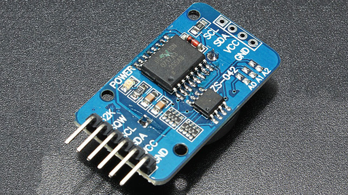
This tutorial is based on the ability and features of the DS3231 RTC module. The DS3231 is a low power RTC chip, it has the ability to keep time with incredible accuracy such that even after power has been disconnected from your project, it can still run for years on a connected coin cell battery. Asides from its ability to accurately keep time, this module also comes with an accurate temperature sensor which will be used to obtain temperature readings during this tutorial.
The main upgrade to the previous tutorial mentioned above is the use of the 1.8″ colored TFT display and details about the features and use of this display have been covered in a recent tutorial here.
Required Component
The following components are required to build this project;
As usual, the exact components used for this tutorial can be bought through the link attached to each of them.
Schematics
We will replace the 16×2 LCD display in the schematics from the previous tutorial with the 1.8″colored TFT display. Connect the components as shown in the schematics below.
Read more: Arduino Real Time Clock with Temperature Monitor
-
What is the main upgrade to the previous tutorial?
The project upgrades by replacing the 16×2 LCD display with an ST7735 based 1.8″ colored TFT display. -
How does the DS3231 module keep time after power loss?
It uses a connected coin cell battery to run for years even when disconnected from the main power source. -
What new feature is added regarding temperature monitoring?
The project now displays the highest and lowest temperature measured over time. -
Does the DS3231 module have a built-in temperature sensor?
Yes, the module comes with an accurate temperature sensor used to obtain readings. -
Which display type was replaced in this specific tutorial?
The 16×2 LCD display shield was replaced with a 1.8″ colored TFT display. -
Can the DS3231 maintain time accuracy without power?
Yes, it keeps time with incredible accuracy even after power has been disconnected.
