Summary of Arduino Projects: Audio VU Meter
Summary (under 100 words): An Arduino UNO–based audio VU meter displays left and right audio signal intensity as bar graphs on a 16×2 LCD. Audio inputs connect to analog pins A2 and A4, are read by the ATmega328, processed and compared, and custom LCD characters show varying bar heights. A 10 kΩ potentiometer adjusts LCD contrast. The Arduino sketch initializes hardware, creates custom characters, reads analog values with analogRead, maps them to bar levels, and continuously updates the display.
Parts used in the Arduino based audio meter:
- Arduino UNO board (ATmega328)
- 16×2 LCD module (JHD162A)
- 10 kΩ potentiometer
- USB A-B cable (for uploading sketch and power)
- Audio source (microphone with amplifier or direct music player output)
- Wiring/jumper wires
- Power supply (USB, AC-to-DC adapter, or battery)

Displayed is an audio meter based on Arduino that utilizes a liquid crystal display (LCD). A VU meter, also known as a standard volume indicator (SVI), is a tool that shows the signal level in audio equipment. This project involves displaying the intensity of left and right audio signals as bars on a 16×2 LCD screen using an Arduino UNO board. The Arduino UNO board’s analogue input pins are utilized in this circuit to measure audio-signal levels.
The Arduino UNO board has analogue input pins A2 and A4 where audio-signal inputs can be connected. These may come in the form of sound from a microphone amplified, or as direct output from a music player.
Arduino based audio meter circuit
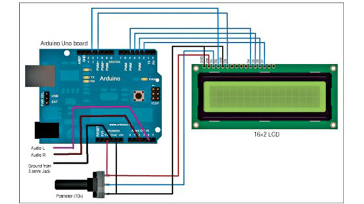
Arduino based audio meter circuit
Audio signals at pins A2 and A4 are processed by ATmega328 microcontroller (MCU) on Arduino UNO board and, after comparing the signals, calculations are done.
Finally, corresponding values are provided by ATmega328 to a 16×2 LCD for displaying audio intensity bars.
The Arduino based audio meter, as shown in Fig. 1, is built around Arduino UNO board, 16×2 LCD and 10-kilo-ohm potentiometer (or potmeter).
Arduino UNO board
Arduino UNO is a prototyping platform for electronics that is open source and relies on user-friendly hardware and software. The Arduino UNO board utilizes the ATmega328 microcontroller. It contains 14 I/O pins, with six capable of serving as PWM outputs, six analog inputs, a 16MHz ceramic resonator, USB connection, power jack, reset button, and an ICSP header. It includes all the necessary components to assist the MCU; just plug it into a computer via a USB cord, or power it up with an AC-to-DC adapter or a battery to get going.
The Arduino UNO board’s pins 11 and 12 are linked to the LCD’s EN and RS pins, and pins 2 to 5 are connected to the 16×2 LCD’s data pins D7, D6, D5, and D4.
LCD 16×2
The JHD162A LCD is a module that utilizes a 4-bit interface to show the bars that represent the level of the input signal. This circuit is only utilizing four of the data pins on the LCD module. A 10-kilo-ohm potentiometer is utilized to adjust the contrast of the LCD screen.
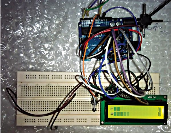
Author prototype of the Arduino based audiometer: Left and right bars displayed on the LCD
Analog input pins A4 and A2 of Arduino UNO board receive analog audio signals for left and right channels. The ATmega328 MCU on the Arduino UNO board processes the signals and then transmits data to the LCD screen to show the signal level bars after conducting comparisons.
The height of the bars will vary depending on the voltage of the audio input signal at pins A2 and A4 of the Arduino UNO board, as illustrated in Figure 2. The LCD shows L for the left channel and R for the right channel. It is important to connect pins A2 and A4 on the Arduino UNO board with caution to ensure the circuit receives the correct audio input channel.
Custom characters are generated for the 16×2 LCD screen in order to show bars, as discussed in the programming section. The potentiometer is utilized to adjust the brightness of the screen and can be changed based on need.
Software program
The program for this circuit performs the following functions:
1. Initialising the circuit and LCD
2. Displaying the welcome message on the LCD
3. Generating custom characters
4. Performing various comparisons with input signal voltage at analog input pins
5. Displaying bars and changing their respective heights on the LCD according to the input signals
The program uses special characters for bar-height display on both rows of the LCD using arrays p3, p4, p5, p6 and p7, and arrays L[8] and R[8] for displaying letters L and R on the 16×2 LCD’s starting columns of both rows, respectively.
Similarly, array K[8] is used for displaying special characters at the end of both rows, and LEEG[8] is used to display special characters for bar shapes.
LiquidCrystal lcd(12, 11, 5, 4, 3, 2) function is used for LCD configuration.
Download source code: click here
void setup()function is used to configure the pins of ATmega328 MCU on Arduino UNO board.
Serial.begin(9600) function is used to configure for serial communication with Arduino board at a baud rate of 9600.
lcd.begin(16, 2) function is used to indicate the size of the LCD.
lcd.createChar(1, p3) function is used to define custom characters for further calling in the program by number only.
LCD.print(“VU METER”) function is used to display the VU meter as a welcome message.
void loop() function is used to perform the task for infinite time.
analogRead(inputPin) function is used for reading the analogue-input value.
Simple calculations are performed to get the values for displaying the bar heights as per audio-input signals.
Construction and testing
A USB A-B cable is used to upload the compiled sketch (software) from the PC to the MCU through Arduino IDE.
Read More Detail:Arduino Projects: Audio VU Meter
- Which Arduino analog pins are used for audio inputs?
The article specifies analog input pins A2 and A4 for the left and right audio signals. - How does the project display audio levels?
The ATmega328 processes analog readings and sends bar-height data to a 16×2 LCD using custom characters to show bars. - What is the role of the potentiometer in the circuit?
A 10-kilo-ohm potentiometer is used to adjust the contrast (brightness) of the LCD screen. - Which Arduino pins connect to the LCD?
Pins 11 and 12 connect to the LCD EN and RS pins, and pins 2 to 5 connect to LCD data pins D7, D6, D5, and D4. - What functions does the software perform?
The program initializes the circuit and LCD, displays a welcome message, generates custom characters, compares analog input voltages, and updates bar heights on the LCD. - How are custom LCD characters created in the code?
The code uses lcd.createChar with arrays (such as p3, p4, p5, p6, p7) to define custom characters for bar display. - What Arduino functions are mentioned for setup and reading inputs?
The article mentions void setup(), Serial.begin(9600), lcd.begin(16, 2), lcd.createChar, void loop(), and analogRead(inputPin). - Can the audio input be from a microphone?
Yes, audio inputs may come from a microphone with amplification or directly from a music player.