Summary of Laser Cut Sphere-O-Bot using Arduino
The Sphere-O-Bot is a simple two-axis CNC that draws on spherical surfaces (ping pong balls, eggs). This laser-cut variant replicates a 3D-printable design with a cleaner look and faster part production, and includes an electronics bay for wiring, microcontroller, and motor drivers. The tutorial covers materials, laser cutting and 3D printing files, frame assembly, and an improved marker gantry design to reduce jitter. It was developed for a kids' workshop where participants build motor controllers.
Parts used in the Sphere-O-Bot:
- 1/4'' plywood (laser cut parts)
- Access to a laser cutter and 3D printer (for parts)
- 9 6-32 screws and nuts
- 8 M3 screws
- Micro sized servo motor
- 2 NEMA 17 stepper motors
- Arduino Uno or comparable board
- Pololu A4988 stepper motor drivers
- Marker (Sharpie or similar)
- 8mm threaded rod
- Wire
- Soldering iron
- Small spherical objects (ping pong balls, eggs, etc.)
- Metal spring
- Optional AC switch
- Optional limit switch
- 3D printed marker holder (holderV2 or original)
- Hinge for marker gantry (or flexible plastic substitute)
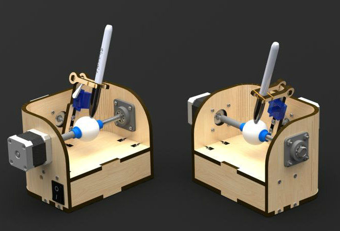
The Sphere-O-Bot is a simple 2 axis CNC machine that can draw on most spherical surfaces. You can use it to decorate ping pong balls or eggs.This design is based on the 3D printable Sphere-O-Bot. By building your Sphere-O-Bot using a laser cutter, you can achieve a clean look while also reducing the production time of your parts. This design also features an electronics bay for your wires, micro-controller, and motor drivers.
The Sphere-O-Bot described in this tutorial was designed for a workshop in which kids get to build their own motor controllers. For more projects by the Maker Corps interns at the Children’s Museum of Houston, visit our site: kidmakers.org
If you like this project, please consider voting for me in the epilog challenge. My internship at the Children’s Museum of Houston will end in a couple of weeks and so will my unlimited laser cutter access. Having a laser cutter of my own will allow me to keep developing more instructables for you. Thanks.
Step 1: Materials
You will need:
- 1/4” plywood
- Access to a laser cutter and 3D printer
- 9 6-32 screws/nuts
- 8 M3 screws
- Micro sized servo motor
- 2 NEMA 17 stepper motors
- Arduino Uno or comparable board
- Polulu A4988 stepper motor drivers
- Marker (Sharpies work well)
- 8mm threaded rod
- Wire
- Soldering iron
- Small spherical objects (ping pong balls, eggs, etc…)
- A metal spring
Optional:
- AC switch
- Limit Switch
Step 2: Laser Cut & 3D Print
Download the design file here and cut it out of the 1/4” wood using a laser cutter.You could probably also cut these out of plexiglass except for the curved part, since it would not be flexible enough.
The 3D printable files can also be found under the same Thingiverse post. The printable files are actually borrowed from this 3D printable Sphere-O-Bot design.
Disclaimer: It’s ok if the renders/pictures in this Instructable don’t exactly match the design file on thingiverse. That just means that I’ve been doing some design changes to help things fit better.
Step 3: Assemble the Frame
Using the 6-32 screws/nuts, join the curved part to the bottom piece. I found that if you insert the screws into the large piece and loosely attach the nuts, you can then bend it around the bottom piece and secure it with ease. Keep in mind that since the wood was originally flat so it will try to fight back against bending.
Now all you need to do to finish the frame is to secure the top and front panels of the electronics bay. BUT WAIT!!! You haven’t installed the electronics yet. Your life will be easier if you don’t attach the last two pieces of the frame until after taking care of the electronics.
Step 4: Marker Gantry
UPDATE: After realizing that the original design suffered from severe jitter, I re-designed the marker gantry to make it more sturdy. Check out this short animation to see how it works and how it is assembled. The micro sized servo is attached using M2 screws and the rest of the screws are M3. The hinge that I used can be found here, but feel free to replace it with any other hinge of a similar size. If you can’t find a hinge, you could probably just glue a flexible piece of plastic between the two main wooden pieces of the marker holder. The file for the new holder design is titled holderV2 in the Thingiverse post.
For more detail: Laser Cut Sphere-O-Bot using Arduino
- What is the Sphere-O-Bot used for?
It is a two-axis CNC machine used to draw on most spherical surfaces like ping pong balls and eggs. - What materials are needed to build the laser-cut Sphere-O-Bot?
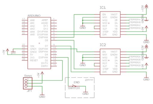
The article lists 1/4'' plywood, screws/nuts, M3 screws, micro servo, two NEMA 17 steppers, Arduino Uno, A4988 drivers, marker, 8mm threaded rod, wire, soldering iron, small spheres, and a metal spring; AC switch and limit switch are optional. - Do I need a 3D printer for this project?
Yes, some parts are 3D printable and the design borrows printable files from the original Sphere-O-Bot Thingiverse post. - Can I laser cut the parts instead of 3D printing?
Yes, the design is intended for laser cutting the wooden parts; some parts remain 3D printed. - How are the curved wood pieces assembled?
Insert 6-32 screws into the large piece, loosely attach nuts, bend the curved part around the bottom piece, and then secure the nuts once positioned. - Should I attach the electronics bay panels before wiring?
No, the tutorial advises leaving the top and front electronics bay pieces off until after installing the electronics to make wiring easier. - What issue was found with the original marker gantry?
The original design suffered from severe jitter, prompting a sturdier redesigned marker gantry (holderV2). - How is the micro servo attached in the marker gantry?
The micro servo is attached using M2 screws, while other gantry screws are M3; a hinge is used for the holder or a flexible plastic substitute can be glued.