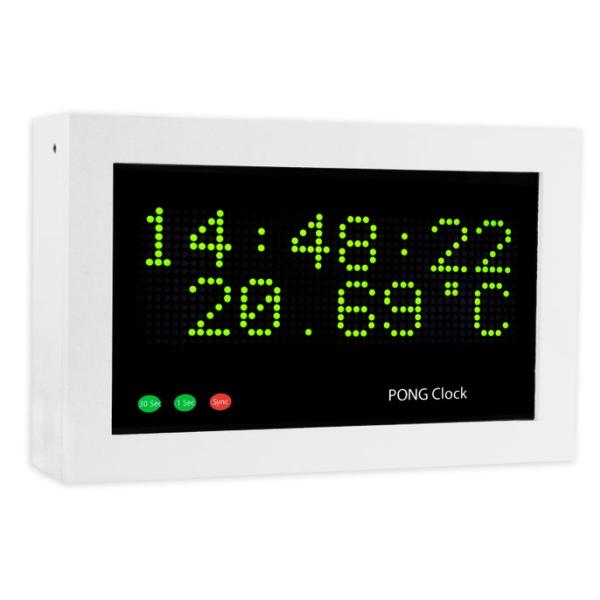
In Pong clock mode the clock uses the classic video game Pong to tell the time The 2 players automatically win and lose so their scores show the hours and minutes. It is based on a clock by Nick Hall.
This is the 2nd version of my clock and now displays temperature in slide mode and also has a timer in normal mode. The 1st version can be found here Pong Clock Mk1 instructable
The clock has lots of different display modes to choose from:
Pong Clock, Large Digits,Time written in words, e.g. “Ten Past Twelve”, Time and date with seconds,Time and date with seconds and a slide effect,
Options-12/24 hour option, Brightness option, Random clock mode option (changes the display mode between Slide with temp and Pong see bottom for details), Daylight saving option to add an extra hour.
Push button driven menus for setup & display selection.
The project uses 2 bright LED matrix panels from Sure Electronics.
You can choose between green or red panels with 3mm or 5mm LED’s .
An Arduino runs the main code and a DS1307 clock chip keeps time, even when the power is off.
Modifications to Nick Hall’s clock
I have made the following changes to Nick’s code/design.
I have removed one of the modes, Time and date with seconds with jumbled character effect to save space on the Arduino.
Instead of the DS1307 RTC I have used a DS3231 AT24C32 I2C Precision Real Time Clock Module.
A PIR is used to turn off the clock display when no one is in the room.
I have also added synchronisation to my Master Clock system if you don’t use this feature then the clock accuracy will depend on your RTC module a DS3231 is far more accurate than a DS1307.
The completed clock has been fitted into a white wooden box with a black display mask printed on inkjet slide film.
Countdown timer added to Normal mode. When countdown is completed an alarm is sounded by playing any 48KHz mp3 file through a JQ6500 sound module
Large numbers of different alerts can be set along with volume from the control panel
Temperature display added to slide mode via an Adafruit MCP9808 High Accuracy I2C Temperature Sensor
The IR remote control is not used in this version but a control panel fitted to a modified mains switch plate is used instead
Random Mode
Random mode has been changed so only my favorite 2 modes Slide and Pong are displayed.
When Random mode is set Slide is displayed from 08:50 to 05:10 and then Pong from 05:10 to 08:50 e.g. 00:00 Slide until 05:10 then Pong until 08:50 then Slide until 15:10 then Slide until 18:50 then Pong until 25:10 etc etc. So when the 1st min digit is 8 and secs are 10 Slide mode is activated until the 1st mins digit is 5 and seconds are 10 Pong mode is activated. This means Slide mode is shown for 6 mins 20 seconds followed by Pong for 3 mins 20 seconds.
Step 1: Pong Clock MK2 Uses
The video shows the different modes of my Pong Clock.
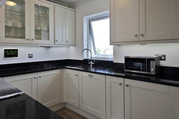
Picture 1 shows the Pong Clock in a kitchen with the control panel hidden away in a cupboard.
Picture 2 shows the pong clock in a seating area with the control panel and PIR panel set into the wall in chrome flush mount boxes.
Step 2: Display Modes
Animation 01
This is the default mode and displays the time and temperature with sliding digits. The temperature is checked every 10 seconds.
Animation 02
This is the timer mode. When in another mode and the Timer/Start button is pressed the clock will jump to this mode. The timer loads with a preset time from code (4 mins as I use it for timing brewing tea). The time can be adjusted using the control panel. If the preset time is OK then press Timer/Start again to start the countdown timer.
On completion of the count down a sound is played and the display returns to the Time and Temperature display.
Animation 03
Pong Clock mode. The clock plays pong with itself missing the ball to update the time every minute.
The time is displayed as the game score.
Animation 04
Word clock mode. The time is displayed as words.
Animation 05
Big Digit clock. In this mode the time is displayed as large digits.
Step 3: Construction Case Preperation
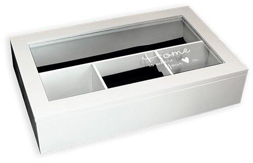
- The case is made from a cheap White Wooden Jewellery Box obtained off ebay
- First scrape off the white lettering from the glass lid using your finger nail or a hard piece of plastic.
- Then carefully pull out the glued in wooden dividers making sure you do not split the case sides.
- Remove the felt ring holders and fit a board a new base board on top of the existing to hide the glued down lining.
- The old mortise slots are tidied up with filler
- A display mask is printed out on clear ink jet film
- The mask is attached behind the glass with thin wooden strips.
- Completed case ready for circuit boards.
- The base of the case is then sprayed black ready for final assembly of the electronics.
Step 4: Construction Mounting Boards/Displays in the Case
Pic 01
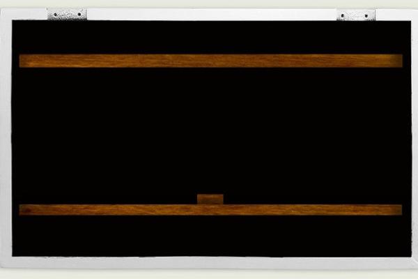
2 off 13x35mm timber battens are fixed across the box using countersunk No4 screws to hold the Sure dot matrix displays.
The top baton is about 23mm from the top of the inside of the case ( or the width of the RTC PCB). Just fix the top baton for now screw from the case sides to the end of the batons. The batons are adjusted up or down so the displays are up to but not touching the display mask. Leave a gap under the batons to allow for wiring.
Pic 02
Fix the main PCB to the base of the box using a couple of short screws leave it clear of the lower wooden baton.
Pic 03
The displays are mounted in the centre of the box foxed with M2 screws and sit on a wooden baton off cut fixed flush to the top of the lower baton. There is not a lot of space on the lower display PCBs so the off cut has to be cut to fit.
Pic 04
The RTC module fits snugly between the top baton and the case. Once the display is fixed to the top baton the position of the lower baton can be found. Fix in place with No4 countersunk screws from the sides of the case. Fix the temperature module in place with No2 screws then fit the LED board in place to align with the text on the display mask.
Pic 05
The lid has two thin timber strips attached by No2 screws to the underside. The glass side of the timber strips seen below are covered with double sided tape. The top strip the tape facing the glass is left on so it does not stick to the display mask but just cushions it in place. The lower strip has both sides of tape exposed. One side stick to the lower baton and the other is stuck to a piece of white paper cut to size. This provides the white background to the display mask text. The double sided tape is cut away around the slot in the lower baton but the paper covering is not cut to act as a diffuser for the LEDs.
The lower baton double sided tape is cut away around the LEDs then the whole strip is covered in white paper (not shown).
Pic 06
Rear view of the lid showing how the timber strips are attached to the lid.
Pic 07
With the lid shut and no mask fitted the timber strips are in place with double sided tape showing ready to be covered in white paper. Note the paper will cover the LEDs and act as a diffuser.
Pic 08
Display mask in place behind the glass held in place by the wooden batons. The white paper stuck to the double sided tape shows through the clear lettering on the display mask.
Step 5: Display Mask

Pic 01
The display mask is printed out onto clear inkjet transparency paper
Pic 02
The mask is cut to fit into the recess in the rear of the lid
Pic 03
Mask fitted in place
Pic 04
Thin strips of wood and tiny M2 wood screws hold the mask in place.
Double sided tape is fixed to the mask side of the tape and white paper is then cut to size and fixed to the tape to stop it sticking to the mask and to give a white background for the clear lettering of the mask.
The lower wooden strip of wood has a square section cutaway so the LEDs can illuminate the 3 pulse indicator lettering.
The strips of wood are cut/fixed so they clear the inside of the case when the lid is closed.
Source: Arduino Pong Clock With Temperature and Timer