Summary of Arduino Police Strobe Light Code
This article details a project to create an Arduino-controlled police strobe light effect. By using two red and two blue LEDs connected to digital pins, the system flashes in an alternating pattern. A 10kΩ potentiometer connected to analog pin A0 allows users to adjust the blinking speed dynamically via code mapping, ranging from 10ms to 500ms delays.
Parts used in the Arduino Police Strobe Light:
- 2x 5mm red LED
- 2x 5mm blue LED
- 1x Arduino
- 4x 330Ω resistor
- 1x 10kΩ potentiometer
- Jumper wire
Arduino Police Strobe Light effect, another simple variation of blink code.
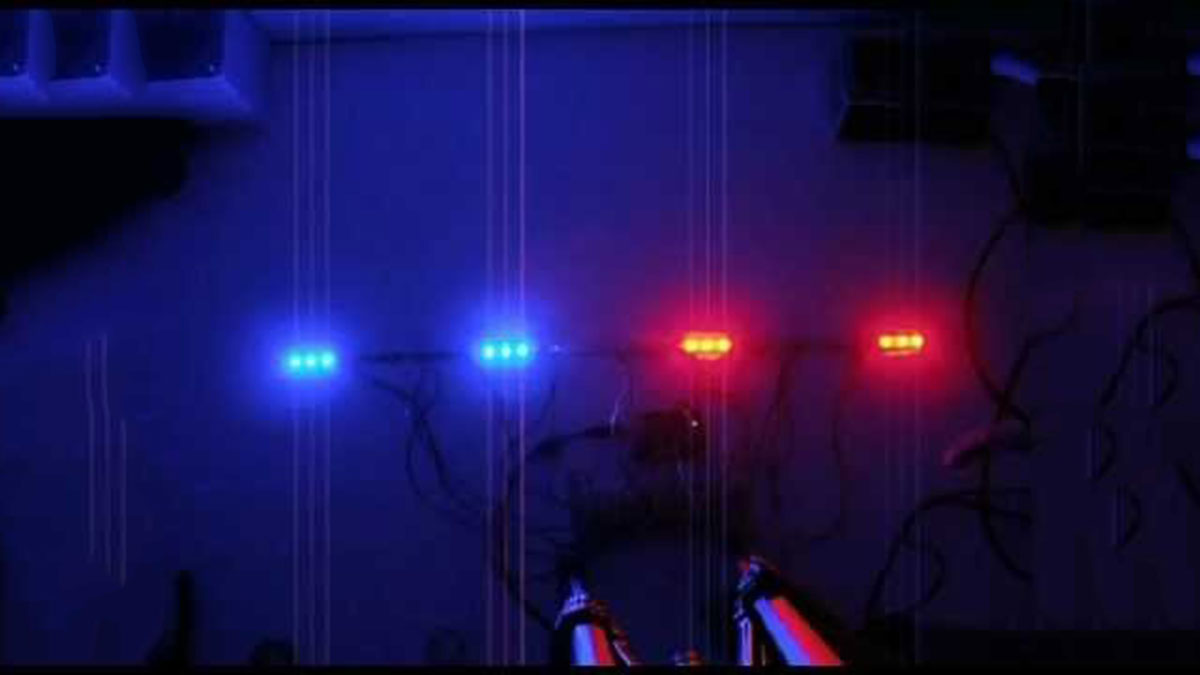
Arduino Police Strobe Light effect, another simple variation of blink code.
Parts List;
1) 2x 5mm red LED
2) 2x 5mm blue LED
3) 1x Arduino
4) 4x 330Ω resistor
5) 1x 10kΩ potentiometer
6) Jumper wire
Instruction;
1) Connect all LED as diagram below, make sure cathode lead of LED at ground wire.
2) Connect all 330Ω resistor to anode lead of LED.
3) Connect all jumper wire to digital pin 12 and 11.
4) Connect 10kΩ potentiometer as shown and center lead connect to analog 0 pin.
Upload this code to your arduino
/*
  Police Strobe Light
  Create police strobe light effect with speed control of the blink.

  Coded by: arduinoprojects101.com
 */
const int analogInPin = A0; // Analog input pin that the potentiometer is attached to
int sensorValue = 0;        // value read from the pot
int timer = 0;              // delay value

void setup() {
  // initialize the digital pin 12, 11 as an output.
  pinMode(12, OUTPUT);
  pinMode(11, OUTPUT);
}

void loop() {
  // read the analog in value:
  sensorValue = analogRead(analogInPin);
  // map sensorValue reading to match timer delay between 10ms to 500ms
  timer = map(sensorValue, 0, 1023, 10, 500);

  digitalWrite(12, HIGH);
  delay(timer);
  digitalWrite(12, LOW);
  delay(timer);
  digitalWrite(12, HIGH);
  delay(timer);
  digitalWrite(12, LOW);
  digitalWrite(11, HIGH);
  delay(timer);
  digitalWrite(11, LOW);
  delay(timer);
  digitalWrite(11, HIGH);
  delay(timer);
  digitalWrite(11, LOW);
}
This arduino projects, is another variation of blink code. delay value controlled by timer constant.
const int analogInPin = A0;
declare where analog input pin from 10kΩ potentiometer, that is analog pin 0 (A0).
sensorValue = analogRead(analogInPin);
reading analog value from analogInPin (A0), analog input reading will give 0 to 1023 integer value.
timer = map(sensorValue, 0, 1023, 10, 500);
timer constant use to control speed of the light strobe blinking. map is use to match analog reading (0~1023) with delay (10ms-500ms). If analog reading is 0, this will map 10ms as delay time, if analog reading is 511, this will map 250ms as delay time and so on.
Source : Arduino Police Strobe Light Code
- How do I connect the LED cathodes?
The cathode lead of each LED must be connected to the ground wire. - Where should the resistors be placed?
All 330Ω resistors are connected to the anode lead of the LEDs. - Which digital pins control the lights?
Jumper wires connect the LEDs to digital pins 12 and 11. - How is the blinking speed adjusted?
The 10kΩ potentiometer center lead connects to analog pin 0 to control the delay timer. - What range does the timer delay cover?
The code maps the sensor value to a delay between 10ms and 500ms. - What happens if the analog reading is 0?
An analog reading of 0 maps to a 10ms delay time for the fastest blink. - Can I change the number of blinks per cycle?
The provided code cycles pin 12 three times and pin 11 three times before repeating. - Does this project require external libraries?
No, the code uses standard Arduino functions like pinMode, digitalWrite, and analogRead.