Summary of ARDUINO PH METER
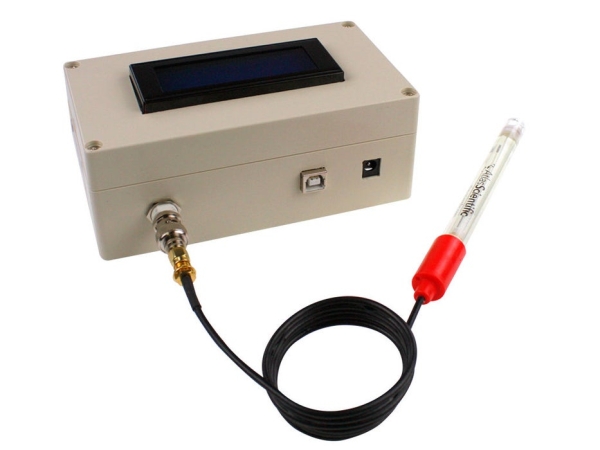
This project builds a benchtop pH meter using an Arduino Uno, an Atlas Scientific Gravity analog pH circuit and probe, and a 20x4 LCD in an ABS enclosure. The guide covers housing modification, mounting an acrylic base plate, installing electronics, wiring with two resistors for LCD contrast, uploading Arduino code and libraries, and calibrating the probe with standard buffer solutions via the serial monitor. Calibration data are stored in EEPROM; temperature compensation is not included (device accurate ±0.2% between 7–46°C).
Parts used in the Benchtop pH Meter:
- Arduino Uno
- Gravity analog pH sensor (Atlas Scientific)
- pH probe
- 20x4 LCD module
- 158x90x60mm ABS enclosure
- Mini breadboard
- Jumper wires
- Acrylic sheet (6.4mm thick, plexiglass)
- 4 x 11mm standoffs and screws (comes with the pH sensor)
- 220Ω resistor
- 1kΩ resistor
- BNC connector (for probe)
- Screws to secure housing and components
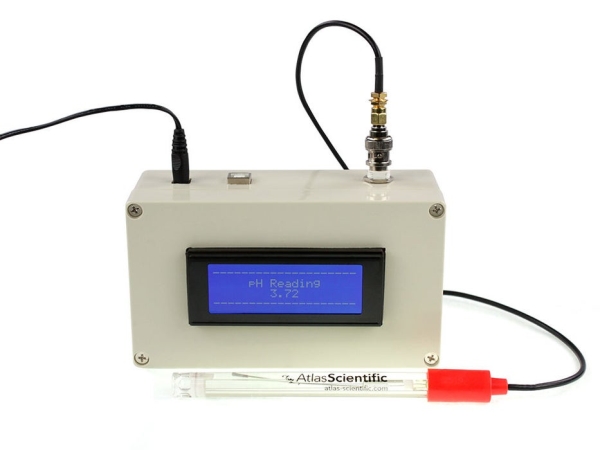
In this project, we will be making a benchtop pH meter using the gravity analog pH circuit and probe from Atlas Scientific and an Arduino Uno. Readings will be displayed on a liquid crystal display (LCD).
MATERIALS
- 1 – Arduino Uno
- 1 – Gravity analog pH sensor
- 1 – pH probe
- 1 – 20×4 LCD module
- 1 – 158x90x60mm Enclosure
- 1 – Mini breadboard
- Jumper wires
- Acrylic sheet (plexiglass)
- 4 – 11mm standoffs and screws (comes with the pH sensor)
- 1 – 220Ω and 1 – 1kΩ resistors
TOOLS
Drill, drill bits, drywall cutter bits, files, screwdrivers, benchtop vise, band saw, glue gun and glue stick, soldering iron and solder, digital caliper, ruler.
Step 1: Prepare Housing
Safety: Remember to take care when handling tools/machinery and to wear proper safety gear such as goggles, gloves, and respirators.
The housing used is an ABS plastic enclosure. It has to be modified for the pH meter.
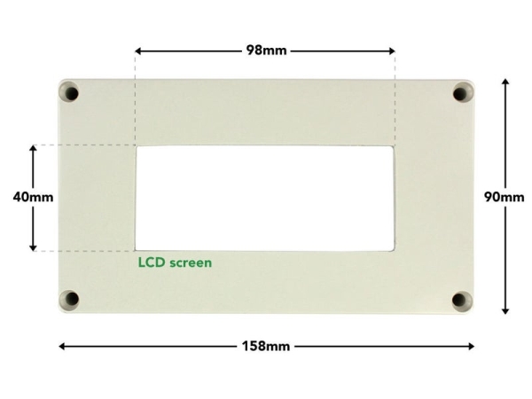
Cut opening for the LCD
a) The LCD is placed in the top portion (cover) of the enclosure. Center a 98x40mm rectangle on the cover.
b) Put the piece in the vise and drill a 3.2mm (1/8″) pilot hole in the rectangle that was marked off.
c) Use this pilot hole as the start point for the 3.2mm (1/8″) drywall cutting bit. Since this a small job, we will use the bit on the hand drill rather than a drywall cutting machine. Work on the inside of the rectangle instead of the lines as it may be a bit difficult to cut in a straight manner with this bit on the drill.
d) Next, use a hand file to remove the excess material and shape the rectangle to the required size.
Cut openings for BNC connector and Arduino ports
The openings for the BNC connector and Arduino ports are on the side of the bottom portion of the enclosure.
a) Using the dimensions provided above, mark the center point for the circle and outlines for the two rectangles.
b) Put the piece in the vice and cut the openings. The circular opening is made using drill bits. The rectangular ones are made by following a similar process used to make the opening for the LCD.
Outfit the base plate to mount components
The base plate is used to mount the Arduino, pH sensor and mini breadboard. 6.4mm (1/4″) thick acrylic sheet is used.
a) Using a band saw, cut the acrylic sheet to 135×62.5mm.
b) Mark off the positions for the four holes as shown. Drill 2.38mm (3/32″) diameter holes. Countersink the holes on one side of the plate to a depth of 3mm and diameter of 4.4mm (11/64″). This is necessary to keep a flat undersurface when the screws are inserted to hold the standoffs.
c) Attach the 11mm standoffs using the provided screws. The pH sensor comes with 4 standoffs and screws. Use two of them for the Arduino.
Step 2: Install Electronics in Housing
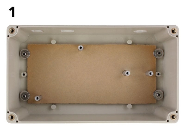
1) Insert the base plate into the bottom portion of the housing. Keep in position with screws or hot glue.
2) Mount the pH sensor on the base plate. Secure to standoffs with screws.
3) Mount the Arduino Uno onto the base plate. Secure to standoffs screws.
4) Add the mini breadboard onto the base plate.
5) Solder the header pins to the LCD (pins provided). Insert LCD into the top portion of the housing and use some hot glue to keep the screen in place.
Step 3: Wire Electronics Together
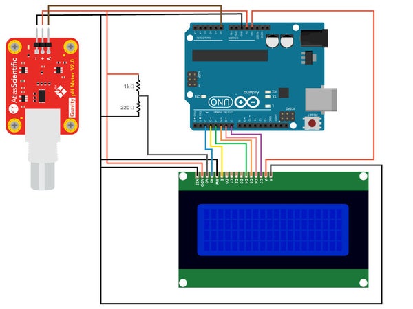
Wire the components are shown in the schematic above.
Use the mini breadboard for the 1kΩ and 220Ω and for distributing the Arduino’s 5V and ground pins.
The two resistors are used to set the screen contrast.
Datasheets
Step 4: Finalize Assembly
After the wiring has been completed:
a) Put the top and bottom portions of the housing together using the provided screws.
b) Connect the probe to the BNC connector.
Step 5: Upload Code Onto Arduino Uno
The code for this project makes use of customized libraries and header files. You will have to add them to your Arduino IDE to use the code. The steps below include the process of making this addition to the IDE.
a) Connect the Arduino to your computer and open the IDE. The IDE can be downloaded from this LINK if you do not have it. Go to Tools -> Board -> Select Arduino/Genuino Uno. Go to Tools -> Port -> select the port where the Arduino is connected to.
b) Add Liquid Crystal Display library: In the IDE go to Sketch -> Include library -> Manage libraries. In the search bar of the Library Manager enter “liquidcrystal”. Look for the package titled “LiquidCrystal Built-in by Arduino, Adafruit”. It may or may not be installed. If not, select the package and click on install.
c) Add Atlas Gravity sensor library: Download the zip file from the following LINK. The file will be saved as “Atlas_gravity.zip”. In the IDE go to Sketch -> Include library -> Add .ZIP Library. Locate the “Atlas_gravity.zip” file and select to add.
d) Next, we have to add the code for the pH meter. Copy the code from this LI NK onto the IDE work panel.
e) Compile and upload the code to the Arduino.
f) The pH readings will then be displayed on the LCD. You can also view the readings on the serial monitor. To open the serial monitor, go to Tools -> Serial Monitor or press Ctrl+Shift+M on your keyboard. Set the baud rate to 9600 and select “Carriage return”.
Step 6: Calibrate PH Sensor
Note: If you plan on using an external power supply for the Arduino, connect it to the Arduino before doing the calibration. This will ensure that the reference levels are appropriately set, which will aid in the correct calibration.
This pH meter can be calibrated to one, two or three-points calibration. Standard buffer solutions (pH 4,7 and 10) are required
The serial monitor is used for the calibration process. The user will be able to observe the gradual change in readings as they come to stabilization and send the appropriate commands.
Calibration data are stored in the EEPROM of the Arduino.
Calibration commands
Low-point: cal,4
Mid-point: cal,7
High-point: cal,10
Clear calibration: cal,clear
Steps
a) Remove the soaker bottle and rinse off the pH probe.
b) Pour some of the pH 4 solution into a cup. Ensure that there is enough to cover the sensing area of the probe.
c) Place the probe in the cup and stir it around to remove trapped air. Observe the readings on the serial monitor. Let the probe sit in the solution until the readings stabilize (small movement from one reading to the next is normal)
d) After the readings stabilize, enter the command cal,4 into the serial monitor. Calibration to pH 4 is now complete.
Repeat steps a-d for pH7 and pH10. Remember to rinse the probe as you proceed to different buffer solutions.
What about temperature compensation?
The sensor used in this project has an accuracy of +/- 0.2%. The pH meter will operate within this accuracy in the temperature range of 7 – 46°C. Outside of this range, the meter will have to be modified for temp compensation. Note: The pH probe can be subjected to a range of 1 − 60 °C.
Read more: ARDUINO PH METER
- What components are required to build the benchtop pH meter?
The project uses an Arduino Uno, Gravity analog pH sensor, pH probe, 20x4 LCD, ABS enclosure, mini breadboard, jumper wires, acrylic sheet, four 11mm standoffs and screws, a 220Ω and a 1kΩ resistor, a BNC connector, and various screws. - How is the LCD mounted in the enclosure?
Cut a centered 98x40mm rectangle in the enclosure cover, drill a pilot hole, use a 3.2mm drywall cutting bit from inside the rectangle, and file to final size, then solder header pins and hot-glue the LCD into the cover. - How are the Arduino and sensor mounted inside the case?
Cut a 135x62.5mm acrylic base plate, drill and countersink four holes, attach 11mm standoffs, then secure the pH sensor and Arduino to the standoffs and add the mini breadboard. - How are the resistors used in the wiring?
The 220Ω and 1kΩ resistors are placed on the mini breadboard to set the LCD contrast and the breadboard also distributes the Arduino 5V and ground. - How do you upload the code and required libraries?
In the Arduino IDE select the Uno board and port, install the LiquidCrystal library via Library Manager, add the Atlas_gravity.zip via Add .ZIP Library, paste the provided pH meter code into the IDE, then compile and upload. - How is the pH sensor calibrated?
Use the serial monitor at 9600 baud with Carriage return; rinse probe, immerse in buffer (pH4, pH7, pH10), wait for stable readings, then send commands cal,4 cal,7 or cal,10; calibration stored in EEPROM. - Can the pH meter perform temperature compensation?
Not by default; the sensor accuracy is ±0.2% between 7 and 46°C; outside that range the meter must be modified for temperature compensation. - How do you view pH readings?
Readings are shown on the 20x4 LCD and can also be viewed on the Arduino serial monitor at 9600 baud.