I have been researching a project which will help me with my understanding of electronics, networking, and programming. I decided to build an online thermometer which could be used in applications that need temperature monitoring. I currently work in a lab environment where I test, troubleshoot, and calibrate equipment which is installed in nuclear power plants . Each module must have a burn in time ranging from 24 hrs to 360 hrs per module under max load conditions. I could use my online temperature sensor to monitor the efficiency of the cooling system in the burn in area.
Other applications could be the monitoring of a server room. The Arduino allows up to 6 sensors to be installed so this would be efficient to monitor a normal sized server room. I could use a program called Pachube to monitor the temperature ranges over time and see where the servers and equipment get the warmest. This could then be tied into another program which could give an administrator a warning e-mail if the room temperature suddenly started rising.
I am going to go step by step in the build of the online thermometer.
I first need a network cable to connect my ethernet shield to a router ( if connecting straight to a computer the cable will need to be a crossover cable).
You will need;
Cat 5 or 6 ethernet cable
Network cable crimper/cutter
Network stripper
RJ-45 data plugs
Start by cutting desired cable length. Use strippers to cut about 1 1/4” from the end.
Spread out twisted pair wires. I aligned them according to the T568B standard because it is more common in the industry. Here’s a diagram of both options and a pinout of a crossover cable.
Allign and pull the wire out while bending the wires back and forth so they are aligned in a tight sequence.
1 Seeed Studio Ethernet Shield or nuElectronics Ethernet Shield with prototyping shield
6 DS18B20 Dallas 1-wire temperature sensors (Note: not DS18S20)
6 4K7 1/4W resistors
Twisted-pair cable or alarm cable (minimum 3 conductors)
1 breadboard
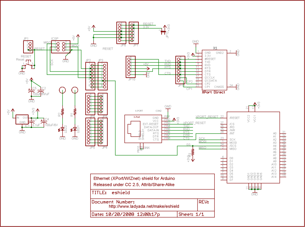
I skipped the first few pins and started with 3 because 0 and 1 are used for the serial connection to the host. Pin 2 is used by the Ethernet shield to communicate with the arduino as seen in Figure 1


