Summary of Arduino M&M Color Sorter
This article details the construction of an automated M&M color sorter using an Arduino Uno, stepper motor, servo motor, and 3D-printed components. The device sorts candies by sensing color via an RGB LED and photo-resistor, then mechanically directing them into six bins. Built with minimal tools, it features a primary mechanism for isolation and initial sorting, and a secondary mechanism for final distribution into a repurposed jam jar.
Parts used in the M&M Color Sorter:
- Arduino Uno
- Stepper Motor (part# 28BYJ-48)
- Stepper Motor Driver (part# ULN2003)
- Servo Motor (part# SG90)
- Limit Switch (part # DBWDKG-FT01)
- Photo-resistor
- RGB LED
- White LED
- 220 Ohm Resistors (4)
- 10 Kilo Ohm Resistor
- 3" 6-32 bolts and nuts (3)
- Jam Jar (Brand: Bonne Mamon)
- Plastic Water Bottle (Brand: SmartWater)
- 0.8mm plexiglass
- M&Ms
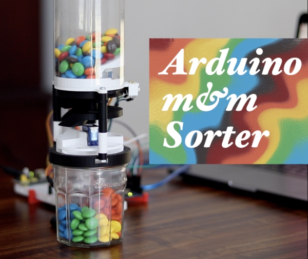
Are you tired of sorting your m&ms by hand? Looking for a silly way to spend your time and 3D printer filament? Then this is the Instructable for you.
This is a project that I built for one of my engineering courses, in which we were challenged to use an Arduino, some basic electrical components, and a 3D printer to build something creative that implemented sensing, actuation, and autonomous sequencing. I chose to tackle the important problem of unsorted m&m candies.
This project took several weeks of testing and iteration, so in this Instructable I will just be explaining my final design, with notes on the design process and tips for how to build one yourself.
Since I was building this project in my apartment with limited access to basic tools, I designed this project to maximize the use of my one tool, the 3D printer. Virtually no other tools are necessary, and the required electrical components are listed below.
Also if you dig this project be sure to vote for it in the Arduino Contest and the Colors of the Rainbow Contest!
Supplies
Arduino Uno
Stepper Motor (part# 28BYJ-48)
Stepper Motor Driver (part# ULN2003)
Servo Motor (part# SG90)
Limit Switch (part # DBWDKG-FT01)
Photo-resistor
RGB LED
White LED
220 Ohm Resistors (4)
10 Kilo Ohm Resistor
3″ 6-32 bolts and nuts (3)
Jam Jar (Brand: Bonne Mamon)
Plastic Water Bottle (Brand: SmartWater)
0.8mm plexiglass
A BUNCH OF M&MS (for experimentation, of course)
Step 1: How to Sense Color
Part of what intrigued me about this concept was that the limited assortment of components I had to work with didn’t include a camera or color sensor, so I would have to devising my own system for sensing color.
On its most basic level, any type of sensor that can distinguish color is just measuring the relative amounts of different wavelengths of light. One of the components I did have at my disposal was a photo-resistor; a resistor that changes resistance based on the intensity of the light it is exposed to. I figured that if I could isolate an m&m in a dark, controlled environment and then use an RGB LED to shine multiple wavelengths of light on it, I could use the photo-resistor to measure the intensity of each reflection, and these values could then be used to distinguish colors.
This is the setup that I implemented, and it worked very effectively. The next step shows the mechanics and orientation of the sensing setup, and the code is detailed later, but I wanted to briefly comment on this system, as it is something that could be further developed in another project.
The code that I wrote for the sensing operation basically just shines the LED at full brightness displaying first red, then green, then blue light, and takes a voltage reading from the photo-resistor during each flash. These values are simply stored as references for each color and then subsequent m&ms are tested in the same way and their values are compared to the references. In other words, the machine just matches responses to references. It cannot, independent of the references, determine the color of a given m&m. In order to create a setup—using photo-resistors—that could detect the RGB composition of a sample, you would have to take into account the variable luminosity of the LED at different wavelengths, as well as the variable response of the photo-resistor to different wavelengths. You would also need to have references for a white and black sample to determine the bounds of the photo-resistor response. This is something I would love to dive into in a further project. @fjordcarver has made some great progress in his Instructable where he explains this process in more detail, and I also think there is potential for using multiple photo-resistors with colored films as an alternative to the LED method. Let me know if you do anything with this concept!
Step 2: Design: Primary Mechanism
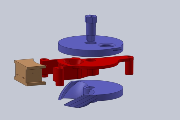
Alright, I’m a mechanical engineering student so this is probably my favorite part of the design. I designed this machine to be compact and vertically oriented for the visual effect of the unsorted m&m’s gradually sifting down into the colored bins below. With this design, each m&m has to be singled out from the upper reservoir, placed into the dark sensing chamber, the chamber has to be shut, and then the m&m must be dispensed from the chamber and directed into one of the six color bins. The fun of it, in my opinion, is that nearly this entire process is accomplished with only one moving part.
I’ll attempt to explain, but it’s easier to just take a look at the pieces and visualize it. The upper disk, lower disk, and center pin connect to form a rotator that spins within the central sensing compartment piece. The central sensing compartment has a chamber that, when an m&m is dropped in the top, funnels it into a controlled position where it can be viewed from the side by the LED and the photo-resistor housed in the sensor housing. The central sensing compartment is stationary, and the rotator is driven from above by a stepper motor mounted in the piece labeled “top layer.” The top layer also serves as the base of the m&m reservoir and houses a limit switch that rides up against a cam on the upper disk.
The sequence starts with the upper disk oriented with the hole 90 degrees counterclockwise from the sensing compartment. At this loading position the upper disk selects an m&m from the reservoir and, rotating clockwise, drops it into the sensing chamber. By rotating 90 degrees more, the chamber is closed on top and bottom, and the sensing operation can be performed in a controlled, dark, environment. Then the rotator turns 180 degrees to return to the loading position and, depending on the direction in which it rotates to get there (clockwise or counterclockwise), the identified m&m will meet one of the two ramps on the lower disk, directing it in one of two directions out of the chamber. In this way the rotator selects the m&m, isolates it for sensing, and sorts it into one of two groups as it selects another. The only remaining action is to further sort from two groups into six groups, which is accomplished by the Secondary Mechanism.
The limit switch and the cam on the upper disk are used to zero the position of the rotator, since the small stepper motor has no feedback and is prone to skipping steps. Additionally, a white LED is mounted in the back of the sensing chamber to aid in detecting if an m&m has been successfully loaded.
Step 3: Design: Secondary Mechanism
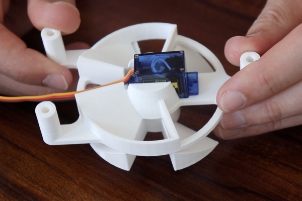
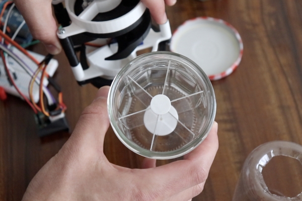
With the identified m&ms sorted into two color groups, the Secondary Mechanism further sorts each group into three colors. The mechanism consists of two ramps that funnel the dispensed m&m into one of two locations on opposite sides of a downward facing servo motor. The servo motor rotates the final divider, which sits above a jar with dividers sectioning it into six 60 degree compartments. Depending on its position, the final divider will direct the m&m either straight down, 60 degrees clockwise, or 60 degrees counter-clockwise to land in the appropriate compartment.
While I was happy with the simplicity and effectiveness of this design, the final divider was modeled to be a bit too shallow. This meant that when rotated to direct an m&m clockwise or counter-clockwise, there was not a lot of clearance and the m&m would occasionally get stuck and not slide through the part. Then, when the divider returned to the middle position, the m&m would fall into the wrong bin. This was a relatively infrequent problem, but it ended up being the only reason for occasional mis-sorts. A redesign of the final divider could fix the issue pretty effectively.
Step 4: Design: Other Components
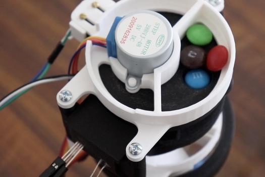
The m&m reservoir is made from the bottom of a SmartWater water bottle, and I modeled the top portion of the machine to fit it snugly. This includes a funnel piece that fits on top of the stepper motor and directs m&ms towards the loading site.
As I was developing the machine, I noticed that the assembly fit nicely on the top of the jam jar that I was using to store my test m&ms. I decided to lean into that idea, and I designed a lid that would allow the whole machine to screw onto the top of the jam jar (brand: Bonne Mamon). I made some clear dividers for the jar by scoring and snapping some 0.8mm plexiglass. These pieces were just held in place with two basic 3D printed parts, and the process of sizing and fitting the dividers was pretty trial-and-error.
Step 5: Assembly Part 1
I modeled all of these parts in SolidWorks and printed them in PLA at 0.28mm layer height on my Ender 3 Pro. I modeled nearly everything to be pressure fit with the components I had, so it is possible that some of the holes and openings on these models may have to be resized if you are working with slightly different components or print settings. In these sections I have included the STL models and technical drawings for all the parts.
Central Sensing Compartment – A white LED is glued into the back of the sensing chamber using hot glue, being careful to say clear of the bottom surface of the part. All the pieces in the Primary assembly are printed in black to minimize reflection, and I also glued in some matte-black construction paper as shown to further minimize reflection within the sensing area. I am not sure if this had a significant effect on sensor accuracy, but I assume it helped a tiny bit. This could also be accomplished by sanding the area to a matte finish or using a matte printer filament.
Sensor Housing – The RGB LED and the photo-resistor are hot glued into the sensor housing piece as shown, which then snaps into the side of the central sensing compartment.
Rotator – The rotator is printed in 3 parts (could be printed in two if you have good print settings). These parts fit together snugly but I also drove in a small screw from the bottom of the lower disk into the center pin for good measure. The disks of the rotator are assembled sandwiching the central sensing compartment as shown.
Top Layer and Funnel – The stepper motor snaps into the top layer facing downwards. The limit switch is fixed on the side of the top layer with two screws that thread through the slots, through holes in the limit switch, and into a small 3D printed part labeled “limit switch holder.” The slots enable the limit switch to be adjusted for optimal contact with the cam. The funnel piece also fits snugly on top of the stepper motor.
Step 6: Assembly Part 2
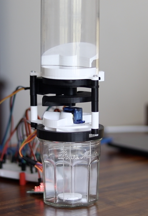
Secondary Mechanism – The servo motor pressure fits into the rectangular hole in the piece labeled “secondary funnel,” and the final divider is attached to the servo arm. If you have worked with these little servos before you’ll probably know that attaching things to them is not that easy. I modeled the final divider with a grove inside of it that fits one of the included servo arms snugly (you’ll have to cut off part of the arm though). Then, I drove in the included screw to secure that arm to the servo rotor. This worked quite well and minimized space.
Full Assembly with Spacers – With all these components printed and mechanisms assembled, everything can now be connected using three 3” 6-32 machine screws and the accompanying nuts. I printed spacers of various lengths to separate each layer of the machine, and while the full assembly drawing includes approximate spacing distances, you will probably have to determine optimal spacer lengths yourself. 3” bolts were longest I had access to, so the machine was designed accordingly. If you have longer bolts, that would give you the freedom to space out the Secondary mechanism a bit more and mount it higher above the jar.
Reservoir and Jar – As mentioned earlier, the reservoir is just a SmartWater water bottle that I cut in half and cut a hole in the bottom of. The top layer and funnel are designed to fit it snugly. The jar is outfitted with plexiglass dividers that fit into the divider holders (3D printed). The plexiglass is 0.8mm thick and you will have to cut it to size according to your jar and the height of the mechanism when screwed on. For permanence the divider assembly can be glued into the jar, but only after you have ensured that it is oriented to line up with the mechanism when screwed on.
Note: aside from the Primary Mechanism being black, you could print these parts in any color. I chose to print in black and white because I liked the aesthetic of the only color on the machine being the color of the m&ms. In my opinion, definitely worth the extra 20$ I spent on filament.
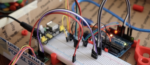
Step 7: Wiring
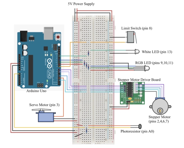
The machine is controlled with an Arduino Uno, and the wiring is pretty simple. I’ve drawn up a nice wiring diagram to specify everything but there are just a few things to note.
– Each LED, including the white LED in the back of the chamber, is wired with a 220 Ohm resistor.
– The limit switch wired to Pin 13 uses the Arduino’s internal pull-up resistor, which must be set in the Arduino Setup routine.
– The photo-resistor is wired in a voltage divider with a 10 Kilo Ohm resistor. Analog pin A0 reads the intermediate voltage from the voltage divider.
– Be sure to power the stepper and servo motors independently of the Arduino (ie. not downstream). Powering the Arduino via USB and powering the stepper from the Arduino’s 5V output will cause problems.
In the future I would love to get all these electronics condensed so they could be mounted on the machine and battery powered, but for this project I didn’t have the time or tools to solder anything and most of the wiring was done on a breadboard.
Source: Arduino M&M Color Sorter
- How does the machine sense color without a camera?
The system uses an RGB LED to shine red, green, and blue light on an M&M while a photo-resistor measures the reflected intensity to distinguish colors. - Can this project be built with only one tool?
Yes, the design maximizes the use of a 3D printer so that virtually no other tools are necessary. - What causes occasional mis-sorts in the secondary mechanism?
Mis-sorts occurred because the final divider was modeled too shallowly, causing M&Ms to get stuck when rotated clockwise or counter-clockwise. - How is the position of the stepper motor maintained accurately?
A limit switch rides against a cam on the upper disk to zero the position of the rotator since the small stepper motor has no feedback. - What materials were used to create the bin dividers?
The dividers were made by scoring and snapping 0.8mm plexiglass to fit inside the Bonne Mamon jam jar. - Why must the motors be powered independently from the Arduino?
Powering the Arduino via USB and the stepper from the Arduino's 5V output will cause problems, so they require independent power sources. - How is the M&M reservoir constructed?
The reservoir is made from the bottom half of a SmartWater water bottle cut to fit snugly onto the top layer and funnel. - What filament settings were used for printing the parts?
The parts were printed in PLA at a 0.28mm layer height on an Ender 3 Pro.