
Summary of 3D Printed Digital Camera
This article guides readers through building a customizable, 3D-printed digital camera. It emphasizes the educational value of understanding device fabrication and the creative joy of a film-camera-like experience without an immediate preview screen. The project involves assembling electronic components like an Arduino Uno and a JPEG camera board, soldering connections, and using 3D printed parts for the body. This DIY approach allows for circuit expansion and custom case design, turning imperfections into unique photographic character.
Parts used in the 3D Printed Digital Camera:
- Files for 3D Printing
- Radioshack JPEG Color Camera Board (Radioshack #276-248)
- Seeed INT106D1P SD shield (Radioshack #276-243)
- Arduino Uno REV 3 (Radioshack #276-148)
- SD card (radioshack #44-188)
- Round PCB Kit (Radioshack #276-004)
- SPST Tactile Switch (Radioshack #275-002)
- Misc. Heat Shrink Tubing (Radioshack #278-1610)
- 9V battery snap (Radioshack #270-324)
- 9V battery (Radioshack #23-853)
- 1/4 x 4-40 bolts
This is a 3D printed digital camera that you can build yourself. By making your own digital camera, it takes away some of the mystery around how such devices work, and are fabricated. Also, it allows you to fully customize the camera to your liking. You can expand the circuit to have new functionality, or design your own custom case by modifying the 123D Design build files.
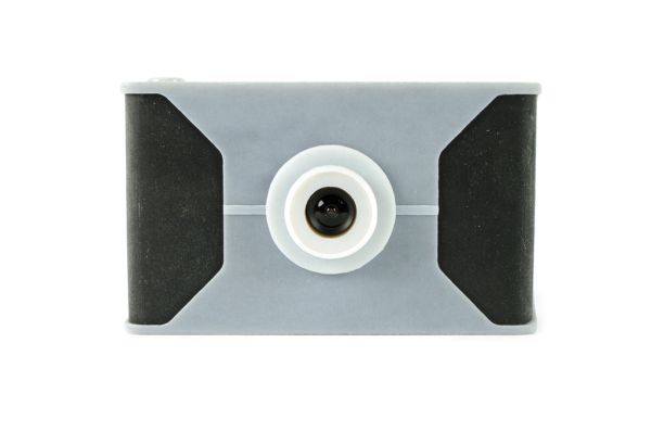
While this may not be a high-resolution digital camera, it is nonetheless very rewarding. This camera allows you to not only build a tool, but be creative with it. Being that this iteration of the camera does not have a screen to preview the pictures, it operates a little bit like a traditional film camera in that you don’t immediately know what the pictures look like. This adds a bit of surprise and excitement when the pictures are finally transferred to the computer from your SD card and you see what has transpired. In the age of immediate gratification, slowing down the creative process adds a bit of magic and mystery to the whole endeavor. In fact, all of the camera’s imperfections and digital glitches give the pictures taken their own unique character. For all of these reasons and more, this camera is a ton of fun to shoot pictures with.
Step 1: Go Get Stuff
You will need:
(x1) Files for 3D Printing (see attached)
(x1) Radioshack JPEG Color Camera Board (Radioshack #276-248)
(x1) Seeed INT106D1P SD shield (Radioshack #276-243)
(x1) Arduino Uno REV 3 (Radioshack #276-148)
(x1) SD card (radioshack #44-188)
(x1) Round PCB Kit (Radioshack #276-004)
(x1) SPST Tactile Switch (Radioshack #275-002)
(x1) Misc. Heat Shrink Tubing (Radioshack #278-1610)
(x1) 9V battery snap (Radioshack #270-324)
(x1) 9V battery (Radioshack #23-853)
(x8) 1/4″ x 4-40 bolts
Step 2: 3D Print
The attached zip file has a set of advanced STLs designed to work with high-end printers (Objet Connex in particular), a set of simple STLs that should work better with consumer-level printers, and 123D Design build files so that you can modify the camera yourself.
That said, 3D print the camera body if you have not done so already.
If you don’t have a 3D printer, you can use a service like Shapeways, i.Materialise, or Ponoko. I recommend sending them the STLs for the conusmer-level printers to ensure you get the correct print.
Step 3: Assemble
Line up the lid with the body of the camera.
Applying gentle and even force, push the pin into the socket for the camera’s hinge until it is flush with the camera body.
Step 4: Insert
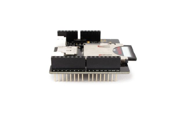
Insert the SD card into the socket on the SD shield.
Step 5: Solder
Solder the tactile switch to the center of the copper pads of the 0.63″ diameter round PCB.
Solder a red wire to one side of the switch, and a black wire to the other side of the switch. If you are unsure which side is which, you can check with the continuity tester on a multimeter.
Step 6: Assemble Button
Slide the camera’s trigger button into place from inside the camera.
Insert the round PCB into the track below the button, such that the top of the tactile switch is directly below the trigger button. They should be touching, but the trigger button should not be applying force on the switch. The switch needs to be able to bounce back after it has been depressed (as we all do).
Step 7: Trim and Solder
Trim the camera module’s male header pins in half.
Solder a 6″ red wire to power, a 6″ black wire to ground, and 6″ colored wires of your choice to both RXD, and TXD. In this example, white is connected to RXD and green to TXD.
Step 8: Install
Take the lens cap off of the camera module.
Insert the camera through the lens hole in the camera body.
Using the corner mounting holes, fasten the camera module to the camera body with 1/4″ x 4-40 bolts.
For more detail: 3D Printed Digital Camera
- How can I customize the camera?
You can expand the circuit for new functionality or design your own custom case by modifying the 123D Design build files. - Does this camera have a screen to preview pictures?
No, this iteration does not have a screen to preview the pictures. - What is the best way to print the camera body if I do not have a printer?
You can use a service like Shapeways, i.Materialise, or Ponoko with the STLs for consumer-level printers. - How do you connect the tactile switch to the circuit?
Solder a red wire to one side and a black wire to the other side of the switch on the round PCB. - What type of wires are connected to the RXD and TXD pins?
In the example provided, white is connected to RXD and green to TXD. - How is the camera module fastened to the body?
The module is fastened using corner mounting holes and 1/4 x 4-40 bolts. - Can you modify the 3D print files?
Yes, the attached zip file includes 123D Design build files so that you can modify the camera yourself. - Why might someone choose to build this specific camera?
It takes away mystery around how devices work, allows full customization, and adds magic by slowing down the creative process.
