Summary of Arduino MKR IoT Carrier As a Game Console
The article details a project turning the Arduino MKR IoT Carrier into a game console by running "BreakIn," a circular Breakout-style game. It covers hardware setup, game physics using an accelerometer for paddle control, collision detection logic, 16-bit color graphics, sprite creation with masks, sound generation via a piezo buzzer, and menu implementation. The guide explains how to use GIMP and online tools to convert images for the display and provides code structure for uploading the game.
Parts used in the BreakIn Game Console:
- Arduino MKR IOT CARRIER
- Arduino MKR 1000 (or any Arduino with the MKR 1010 form factor)
- Arduino IDEA 3.7 V LiPo battery
- GIMP software
- Online services for converting images to C code
In this instructable I’m exploring the capabilities of the MKR IoT Carrier as a game console. The Carrier has everything and a bit more you need for a proper game console.
- A really cool circular colour display, width 256 pixels.
- Five touch buttons. Five RGB LEDs.
- A piezo buzzer.
- A 3 axis accelerometer.
A few other things I won’t use here. The name includes IoT (Internet of Things), but the Carrier doesn’t contain the hardware for net communication. You have to choose a suitable microcontroller board for connecting to internet, f.i. Arduino MKR WiFi 1010. In this project I’m using an Arduino MKR 1000, but I won’t go into IoT aspects of game development.
After reading this instructable you should have a pretty good understanding about how to write a game for the Arduino MKR IoT Carrier. Or you can just take my code and develop it further.
BreakIn
For this instructable I designed a new game. BreakIn is a Breakout game, where the world has been turned inside out. The paddle turns endlessly in a circular path along the edge of the display. The paddle is controlled by tilting the device. The tiles to break are in a hexagonal pattern in the middle, the honeycomb. A perfect game for a circular display and a circular device like the MKR IoT Carrier.
Quick jump to the game
If you have an Arduino MKR IoT Carrier and an Arduino board and just want to play the game, scroll to the chapter “The code, uploading the game to your device” to download the game and start playing. In fact, you should really do it. After that, reading this instructable will make more sense.
Chapters in this Instructable
- Game Physics and Maths
- Collision Geometry
- The Honeycomb Bitmap
- Working With 16 Bit Colour
- Creating and Using a Sprite
- The Sprites in Action
- A Few Things About Sound
- Writing text elements
- Simple menu
- The code, uploading the game to your device
Game design concepts explored
- Accelerometer as a game control
- 16 bit colour graphics
- Sprites
- Pixel based collision detection
- Sounds
- Menu handling
Supplies
- The Arduino MKR IOT CARRIER
- An Arduino MKR 1000 (or any Arduino with the MKR 1010 form factor)
- The Arduino IDE
- A 3.7 V LiPo battery
- GIMP
- Online services for converting images to C code
Step 1: Game Physics and Maths
The screen is logically a 256 by 256 pixel squared colour display. Physically it’s spherical and the logical coordinate of the centre of the sphere is 128, 128. If you are used to orientate on a screen, where the upper left corner pixel is 0, 0, it takes time to start thinking there is no upper left corner. There are no corners at all. Focus on the middle at 128, 128 instead.
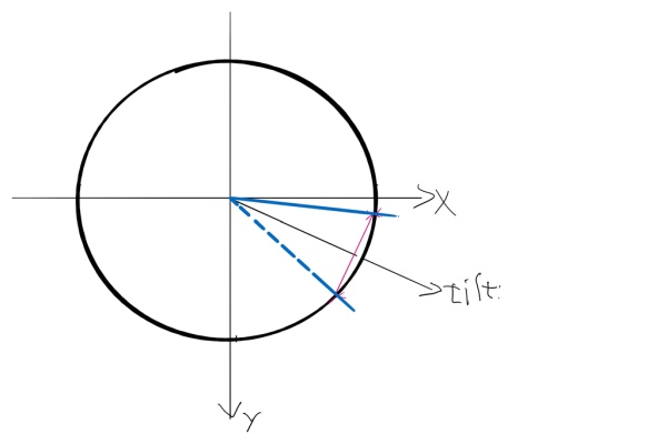
The bat
The bat has a length. It is a simple line, one pixel wide, with a starting point and an ending point at a circle with the middle point at 128, 128 and a radius of 110. The position of the bat is determined by the angle of the tilting of the device. The coordinates of the start and end points of the bat are calculated as follows:
 lx1 = ox+cos(aold-0.2)*110;
        ly1 = oy-sin(aold-0.2)*110;
        lx2 = ox+cos(aold+0.2)*110;
        ly2 = oy-sin(aold+0.2)*110;
…where ox and oy are the screen middle point (128, 128), aold is the angle of the tilt, 0.2 is half of the angular size of the bat (the blue sector in the image).
The tilt angle
The tilt angle can be defined only if the device is not horizontal. The accelerometer of the MKR IoT Carrier measures three axes, x, y and z. When you stare at the display, x-axis goes to the right, y-axis goes upwards and z-axis goes in the direction of your sight. We are interested in x and y. When the device is horizontal, both x and y are zero and no angle can be calculated. When the device is tilted, both x and y change. The angle is calculated as follows:
carrier.IMUmodule.readAcceleration(x, y, z);
      h2 = x*x + y*y;       // squared value of tilt magnitude
      if (h2 > 0.000001)    // if there's a slightest tilt, we can proceed
      {
        a = atan2(y, x);    // a is the angle of the tilt
        delta = a - aold;   // compare it with the previous calculated tilt
        if (delta < -3.1415926536) delta += 6.28318530718;
        if (delta > 3.1415926536) delta -= 6.28318530718;
        h = sqrt(h2);       // "linear" value of tilt magnitude
        if (h > 1) h = 1;
        aold += h*delta;    // change the old value towards the last measured tilt
This is a rudimentary filter to make the bat move somewhat smoothly. A few variables to adjust, if one wants another kind of behaviour. Right now, the bat is very fast and has no inertial momentum.
The honeycomb and the ball
A rectangular set of tiles would have looked dull in the circular screen, so I created the hexagonal honeycomb instead. Each cell is kind of spherical. Each pixel colour is calculated to give a spherical outlook. Because of the hexagonal geometry, every second row has different looking bitmaps for the spheres. The even rows (0, 2, 4…) have 4*4 pixel spheres, the odd ones have 5*5 pixels. Because of the resolution and the correct pixel colours, all look the same. There are 61 cells.
The ball moves at a speed of 0.76 pixels per game loop. The ball bitmap is 3*3 pixels.
The collision detection goes as follows. For each new position of the ball, check whether the corner pixels of the ball will be placed on a pixel not equal to black. If that’s the case, a cell in the honeycomb is hit. Figure out which cell it is and get the coordinate of the cell – that is the centre of the cell. The 5*5 pixel cells have a definite centre pixel. But the 4*4 cells have a “subpixel” as the centre. Subpixels are ok here, because the ball itself has a coordinate on a subpixel. The coordinates and the velocity of the ball are all floating point values. Only when drawn, they are rounded to nearest pixels. The collision detection could be about calculating distances between the ball and each cell, which would lead to more accurate bouncing geometry. But just checking pixels is way faster.
The ball can hit two cells at the same time – at least when only pixels are checked. If that is the case, calculate the mean point between the two cells and have the ball collide against that. Again, a very quick and dirty trick to avoid supercomplex calculations.
So the ball has a velocity and a coordinate. And it hits against a cell with a coordinate. From the two coordinates we get a straight line and a normal to that line. In the next step I describe the bouncing geometry.
Step 2: Collision Geometry
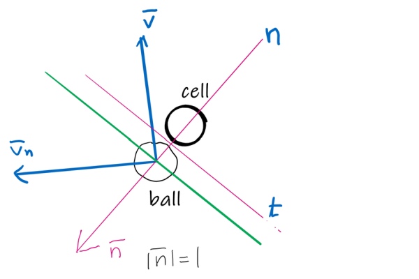
Ball vs. cell
We have a lot of vector arithmetics here. n is the line through the cell and the ball at collision time. t is a perpendicular line to n through the collision point. v̅ is the speed vector of the ball. n̅ is a vector with direction of n and length 1 (a unit vector). v̅ₙ is the new speed vector of the ball after bouncing off the “wall” defined by t.
The bouncing goes like this:
The ball approaches with the velocity v̅. At the collision moment, the line t is defined as a tangent to the colliding spheres running through the collision point. The normal n is defined as perpendicular to t. We need to find the new velocity of the ball, v̅ₙ.
From this page we learn that v̅ₙ = v̅ – 2 * (v̅ · n̅)n̅, where v̅ · n̅ is the dot product of v̅ and n̅, where n̅ is a vector with length 1 and with the direction of line n from the cell to the ball.
In code, it looks like this:
                ny = bally - coly; // colx, coly is the center of the colliding cell
                nx = ballx - colx; // nx, ny is the vector from cell to ball
                l = sqrt(nx * nx + ny * ny);
                nx /= l;
                ny /= l;           // now its length is 1
                dotp = 2. * (vx * nx + vy * ny); // double dot product
                nx *= dotp;
                ny *= dotp;
                vx -= nx;
                vy -= ny;          // Now we have reflected the velocity against the normal
Ball vs. bat
When the ball approaches the bat, we calculate the cross product of the vectors from the ball to each end point of the bat. A cross product is defined as a vector perpendicular to both vectors “being crossed” (gosh, I love speaking maths in a completely non professional way). When the ball is on the right side of the bat, the result vector goes in one direction. Exactly at collision, the result vector is zero. When the ball passes the bat, the result vector goes in the other direction. In our case, we check the z component of the result vector, which goes from – to + when the ball has crossed the bat. Nope, we don’t aim for the exact moment when the collision happens. Think of the bat being a bit elastic. The code looks like this:
        // check ball vs. bat
        if ( (quarantene > 5) && (lx1 - ballx)*(ly2 - bally) - (ly1 - bally)*(lx2 - ballx) > 0) // cross product
        {
          // if cross product is positive, we've crossed the bat line
The quarantene is a counter. It is zeroed when a bat hit happens. After that it increments at each game loop. The whole bat collision control is put in quarantene for 5 loops to avoid annoying repetitive hitting the bat, when the ball doesn’t immediately escape the wrong side of the bat.
So far we only know if the ball has crossed the line. We want to know whether we hit the bat or missed it. If we hit the bat (and the ball is now on the other side of the bat), we can see that the angle between the two vectors is way over 90 degrees. But if we missed the bat, the angle is very narrow. A narrow angle (< 90 degrees) results in a positive dot product, a wide angle (> 90 degrees) results in a negative dot product. Hence:
          if ((lx1 - ballx)*(lx2 - ballx) + (ly1 - bally)*(ly2 - bally) > 0) // if dot product > 0 you missed the bat
          {
            // reset
            newBall();
          }
          else // You hit the bat
          {
            // Do the bouncing off the bat
            float nx, ny, l, dotp;
            ny = lx2 - lx1;
            nx = ly1 - ly2;
            l = sqrt(nx * nx + ny * ny);
            nx /= l;
            ny /= l;
            dotp = 2. * (vx * nx + vy * ny);
            nx *= dotp;
            ny *= dotp;
            vx -= nx;
            vy -= ny;
            quarantene = 0; // Put ball in quarantene for 5 game loops to avoid stucking
          }
The game loop has two places, where a ball is missed. One, if the ball distance from the middle exceeds 128 – the ball could still be “on the right side of the bat”. Another, when the ball misses the bat, even though it still is on the screen. Both are needed, depending on how we place the bat. Right now the bat distance from the middle is 110 pixels. So if the ball is at distance 115 pixels, it has obviously missed the bat, but we like to see it yet, before the game stops for a new ball.
Step 3: The Honeycomb Bitmap
The MKR IoT Carrier comes with a library based on the Adafruit graphics. Without digging and tweaking deeper in the library, there was no way for reading pixel data from the circular screen of the Carrier. Well, at least getPixel() wasn’t available.
But what was available was a GFXcanvas16 structure. It is a bitmap, where one 16 bit word (two bytes) is reserved for each pixel.
Such a bitmap, width 44 and height 40, is defined as:
GFXcanvas16 centre(44, 40);
Now you can draw to this bitmap using the same functions as when you draw to the screen. But you can also read each pixel to check its colour. To draw our honeycomb bitmap to the screen, we do:
carrier.display.drawRGBBitmap(ox - 21, oy - 19, centre.getBuffer(), 44, 40);
The bitmap upper left corner is -21, -19 off the center of the screen. And when we want to know if the ball has hit a cell in the honeycomb, instead of reading the pixels from the screen, which we can’t, we read corresponding pixels from the honeycomb bitmap. We check each corner of the ball. If the corner coordinate is inside the rectangle where the honeycomb is drawn, we read the corresponding x, y pixel from the bitmap like:
  if (centre.getPixel(x, y) != 0)
    {  // Ok, we have a collision. Deal with it.
A collision means the cell has to be deleted. Knowing what pixel we collided with, we know what cell is to be deleted. We just draw a black rectangle over it and draw the bitmap again onto the screen:
  fy = y / 9;
  mfy = y % 9;
  if (mfy < 4) // rows 0, 2, 4...
  {
    fx = x / 5;
    *coly += 9 * fy + 1.5;
    *colx += 5 * fx + 1.5;
    centre.fillRect(5 * fx, 9 * fy, 4, 4, BLACK);
  }
  else         // rows 1, 3, 5...
  {
    fx = (x - 2) / 5;
    *coly += 9 * fy + 6;
    *colx += 5 * fx + 4;
    centre.fillRect(5 * fx + 2, 9 * fy + 4, 5, 5, BLACK);
  }<br>...
  carrier.display.drawRGBBitmap(ox - 21, oy - 19, centre.getBuffer(), 44, 40);
Step 4: Working With 16 Bit Colour
A colour display can set each pixel to any colour. Almost. It blends certain amounts of red, green and blue to achieve as many colours as possible. The MKR IoT Carrier has a 16 bit colour display, meaning a 16 bit word describes each pixel colour. The lowest value is 0, which is black. The highest value is 65535, which is white. Our decimal numbers don’t reveal very well what colour each value is. As hexadecimal words we get 0x0000 for black and 0xFFF for white. For some reason, colours are defined as hexadecimal words, like this:
#define BLACK    0x0000
#define BLUE     0x001F
#define RED      0xF800
#define GREEN    0x07E0
#define CYAN     0x07FF
#define MAGENTA  0xF81F
#define YELLOW   0xFFE0
#define WHITE    0xFFFF
It’s still not quite obvious for a reader what colour a hexadecimal word is. I mean, what colour is 8B7D? But if you are good at blending RGB colours, you can define the colours directly as binary numbers instead. If you are unsure, use your favourite graphic editor, blend your colours and read the RGB values and convert them to red (0 – 31), green (0 – 63) and blue (0 – 31) values. I wanted a pink colour. I knew I get a pinkish colour with full red and say 75% green and 75% blue. Full red with five bits is 11111. 75% green with six bits is 110000. And 75% blue with five bits is 11000. So, putting them together, I get:
#define PINK 0b1111111000011000 // Divided for clarity: 11111 110000 11000
So, one word is four hexadecimal digits. One hexadecimal digit is four binary digits or four bits. That makes 16 bits for one word, hence 16 bit colour. Use #defines in your code and write the colour values as binary numbers, for readability. It only makes your code files larger, not the final program file! If you are new to binary numbers, now is the right time to learn!
Step 5: Creating and Using a Sprite
A sprite is a picture element you want to place on the screen. When placing the element on the screen, the screen might already have some background image. And your new picture element might not be a rectangular image, but a cartoon figure with a distinctive outline. A typical sprite still is a rectangular image, but it might contain transparent parts to allow the background be visible. Each pixel of a sprite is therefore defined by the level of red, green, blue and transparency it has. In the 16 bit colour system of the Carrier display (or actually the Adafruit graphics library the Carrier uses), each pixel is defined as a 16 bit word. All 16 bits go to the red, green and blue colours. There are colour formats, where one bit is stolen from the green channel, leaving green with only 5 bits like red and blue have. This one bit tells whether the pixel is transparent or not. But since our library gives 6 bits to the green channel, another way of determining the transparency is used. Transparency doesn’t really make sense in the screen pixels. They make more sense in images held in memory to be placed over each other on the screen.
Masked sprites
So we have a 16 bit full colour image defined in a bitmap. We can call it the main image. To be able to tell which parts are transparent, we need another image with same size, but with 1 bit colour depth. This image we call the mask image. Each pixel has only one bit! 0 means the corresponding pixel in the main image is transparent, 1 means the pixel is opaque. Drawing a sprite to the screen goes like this:
carrier.display.drawRGBBitmap(100, 30, hccell, hccell_mask, 26, 29);
On coordinates 100, 30, we draw the 16 bit bitmap named hccell. We use the 1 bit bitmap named hccell_mask as the masking bitmap. The size of both bitmaps is 26 pixels wide, 29 pixels high.
The bitmap named hccell needs to be a 16 bit word array in the program memory. It will be declared like this:
const uint16_t hccell[] PROGMEM = {
  0xefff, 0x03ff, 0x87ff, 0x03ff, 0x01ff, 0x03fe, 0x00ff, 0x03f8, 0x003f,
  0x03e0, 0x001f, 0x03c0, 0x000f, 0x0300, 0x0001, 0x0000, 0x0001, 0x0000,
  ...
};
What we have here is a bunch of 16 bit words. Each word defines the colour of one pixel in the bitmap.
The bitmap named hccell_mask needs to be an 8 bit byte array in the program memory. It will be declared like this:
const uint8_t hccell_mask[] PROGMEM = {
  0x00, 0x1e, 0x00, 0x00,
  0x00, 0x7f, 0x00, 0x00,
  0x00, 0xff, 0xe0, 0x00,
  ...
};
Here we have a bunch of bytes. Each byte is 8 bits. Each byte define 8 pixels whether they are transparent or opaque. To my knowledge, the first byte in the array defines an 8 pixel vertical row at the top left corner. Next byte is the next 8 pixel verttical row to the right. But we don’t really need this detail.
PROGMEM refers to program memory. The Adafruit graphics library seems to allow bitmaps being saved in either the program meomory or the SRAM, where variables normally go. The program memory is usually much larger and therefore images are usually placed there. Other libraries (like Arduboy) require the images to be in the program memory.
When we define images in the code as word or byte arrays, they are in the program memory in the first place. Without the keyword PROGMEM, the images will be copied to the SRAM when the program launches. This might speed up the drawing processes, but it will not save program memory. The images are still there.
We need software for creating the sprites as image files (BMP or PNG). We also need software for converting the image files into C code containing the word or byte arrays.
- For drawing the sprites I use Gimp.
- For creating the 16 bit image arrays I use the online tool ImageConverter by Henning Karlsen, or its downloadable version found here.
- For creating the 8 bit masks I use https://lvgl.io/tools/imageconverter.
Creative process
Design your sprite in your favourite graphic editor. You might want to select the same background colour as in your game. In our case it’s black. Save your image in full colour using bmp format, which will restore each pixel without quality loss. It has to be in 24 bit colour, not 32 bit colour. Using the colour selection tool, select the black background. If the tool has a threshold value, set it to zero. Note that only complete black pixels are selected. Now invert the selection. Now you have your sprite character selected. Fill it with white. Save this image as your mask. It can be in same 24 bit colour, even though it only has white and black.
Next thing is to convert the images to c code. Using Henning’s ImageConverter I get a c file looking something like this:
...
#if defined(__AVR__)
    #include <avr/pgmspace.h>
#elif defined(__PIC32MX__)
    #define PROGMEM
#elif defined(__arm__)
    #define PROGMEM
#endif

const unsigned short mysprite[4929] PROGMEM={
0x0000, 0x0000, 0x0000, 0x0000, 0x0000, 0x0000, 0x0000, 0x0000, 0x0000, 0x0000, 0x0000, 0x0000, 0x0000, 0x0000, 0x0000, 0x0000,   // 0x0010 (16) pixels
0x0000, 0x0000, 0x0000, 0x0000, 0x0000, 0x0000, 0x0000, 0x0000, 0x0000, 0x0000, 0x0000, 0x0000, 0x0000, 0x0000, 0x0000, 0x0000,   // 0x0020 (32) pixels
...
I only want the stuff starting with const unsigned short… and ending with }; That is the image data. Each element is a 16 bit word defining one pixel. I copy-paste the stuff into my program. I like to change unsigned short to uint16_t, which is basically the same. And the number inside the square brackets (4929 here) is not needed. Empty square brackets is enough.
Next I do the same with the mask image, but with another tool. The reason for the different tools is that the image is full colour with an array with 16 bit words (uint16_t). The mask is a 1 bit image with an array of bytes (uint8_t). And I haven’t found one tool which could do both the 16 bit colour image and the 8 bit mask image.
So, I use the LVGL tool at https://lvgl.io/tools/imageconverter. I do:
- Image file: I search for the mask image to my sprite
- Name: I name it mysprite_mask to remember what image this will be a mask for
- Color format: Indexed 2 colors
- Output format: C array
- Dithering: Don’t check this
Clicking on Convert will give you something like this:
...
const LV_ATTRIBUTE_MEM_ALIGN LV_ATTRIBUTE_LARGE_CONST LV_ATTRIBUTE_IMG_HC1_MASK.C uint8_t mysprite_mask.c_map[] = {
  0x42, 0x47, 0x52, 0xff, 	/*Color of index 0*/
  0x00, 0x00, 0x00, 0xff, 	/*Color of index 1*/

  0x00, 0x00, 0x00, 0x00, 0x00, 0x1f, 0x00, 0x00, 0x00, 0x00, 0x00, 0x00,
  0x00, 0x00, 0x00, 0x00, 0x00, 0x1f, 0x80, 0x00, 0x00, 0x00, 0x00, 0x00,
...
This is an indexed 1 bit image with each byte defining 8 pixels. First we have four bytes telling the colour of each pixel where the bit is 0, then four bytes thelling the colour for each pixel with bit 1. These two lines we don’t need! We’re only interested in the rest of the array. We copy the data to a new image data array in our code, preferably immediately after the image we created earlier:
const uint8_t mysprite_mask[] PROGMEM = {
  0x00, 0x00, 0x00, 0x00, 0x00, 0x00, 0x00, 0x00, 0x00, 0x00, 0x00, 0x00, 0x00, 0x00, 0x00, 0x00, 0x00, 0x00, 0x00, 0x00, 0x00, 0x00, 0x61, 0x31, 0xc2, 0x6a, 0xc1, 0x41, 0x20, 0x08, 0x00, 0x00, 0x00, 0x00, 0x00, 0x00, 0x00, 0x00, 0x00, 0x00, 0x00, 0x00, 0x00, 0x00, 0x00, 0x00, 0x00, 0x00, 0x00, 0x00, 0x00, 0x00,
  0x00, 0x00, 0x00, 0x00, 0x00, 0x00, 0x00, 0x00, 0x00, 0x00, 0x00, 0x00, 0x00, 0x00, 0x00, 0x00, 0x00, 0x00, 0x60, 0x10, 0x02, 0x73, 0x24, 0xc5, 0x06, 0xde, 0xa6, 0xcd, 0x46, 0x94, 0xe2, 0x41, 0x00, 0x00, 0x00, 0x00, 0x00, 0x00, 0x00, 0x00, 0x00, 0x00, 0x00, 0x00, 0x00, 0x00, 0x00, 0x00, 0x00, 0x00, 0x00, 0x00,
  ...
  0x00, 0x00, 0x00, 0x00, 0x00, 0x00, 0x00, 0x00, 0x00, 0x00, 0x00, 0x00, 0x00, 0x00, 0x00, 0x00, 0x00, 0x00, 0x00, 0x00, 0x00, 0x00, 0x61, 0x31, 0xe5, 0x83, 0x66, 0x9c, 0x61, 0x31, 0x00, 0x00, 0x00, 0x00, 0x00, 0x00, 0x00, 0x00, 0x00, 0x00, 0x00, 0x00, 0x00, 0x00, 0x00, 0x00, 0x00, 0x00, 0x00, 0x00, 0x00, 0x00,
};
Note that this datatype is uint8_t.
To use this, you need to check the image size in your graphic editor you used for creating the image files. Or you might find the data at the end of the c file of the mask you downloaded:
...
  const lv_img_dsc_t hccell_mask.c = {
  .header.always_zero = 0,
  .header.w = 96,
  .header.h = 107,
  .data_size = 1292,
  .header.cf = LV_IMG_CF_INDEXED_1BIT,
  .data = mysprite_mask.c_map,
};
Width 96, height 107 it says. That code snippet is a part of the LVGL graphic system, which we don’t use here. We just use the data we get from their converter. That said, the LVGL could be a nice alternative to use for all graphics on the MKR IoT Carrier.
So we have the mysprite which points to the colour image as a word array. And we have the mysprite_mask which points to the sprite mask, which is a byte array. Then we do:
carrier.display.drawRGBBitmap(100, 30, mysprite, mysprite_mask, 96, 107);
Step 6: The Sprites in Action
So I have this honeycomb of 6 cells in the start screen. And the cells are drawn with one single sprite 6 times. And some of them get deleted. Because the cell is a hexagon and not a rectangle, it has to be drawn as a masked sprite, so it will fit in the hexagonal tiling pattern. Without a mask, each time I draw the cell, the black corners of the rectangle would draw over previous content in the image.
The bumble bee
The image of the bumble bee is larger than the bee. There’s some 5 pixel of black around the bee. With that I can have the bee move across the screen. Each new position is not more than 5 pixels away from the previous position. The sprite will cover its trail. But when the bee hits the honeycomb, the black frame would look ugly covering the yellow cells. For this I need a mask. While moving to the right, the bee has one mask taking care of covering the trail at the left, but defining the contour of the wings of the bee at the right. Two other masks are used for the bee moving up and down.
The start screen
The start screen sequence seen in the video goes through the following:
- Draw the title
- Draw the cells in the honeycomb one by one
- Animate the bee hitting one cell, deleting the cell, beeping, bouncing off
- Repeat by hitting two cells
Abort if key is pressed.
To figure out the coordinates for placing everything and to figure the start and end coordinates for each bee flight, I placed each sprite in one 256 by 256 pixel image in Gimp. I moved the sprites around as independent layers and read the crucial coordinates from there. The size of the bee sprite is 48*32. The first flight happens from coordinate 256, 90 to 169, 102. At each frame in the flight the bee travels 3 pixels. So I did it like this:
  // Bee flies in from right
  for (int i = 256; i > 169; i-= 3)
  {
      carrier.display.drawRGBBitmap(i, map(i, 256, 169, 90, 102), littlebee, littlebee_maskl, 48, 32);
      delay(1);
      carrier.Buttons.update();
      if (carrier.Button1.getTouch())
        return 1;
      if (carrier.Button2.getTouch())
        return 2;
  }
The map() function calculates the y coordinate for each x coordinate. Since the movement is from right to left, I use the bitmap littlebee_maskl as the mask, which will place the bee nicely over the yellow cells while it approaches from the right. But the sprite will paint over with black the previous remains of itself at the right edge. During the loop, we continuously check for button presses, which will end the start screen.
When the bee reaches the position 169, 102, it covers parts of the right most cell of the honeycomb. At this moment we beep and erase the honeycomb with:
  if (soundOn) carrier.Buzzer.sound(B4);
  carrier.display.drawBitmap(HCX+54, HCY, hccell_mask, 26, 29, BLACK);
The beep is silenced later. The hccell_mask, which we created for drawing the honeycomb cells, come in handy, when we want to erase them. We simply use the drawBitmap() function, which simply draws a one colour bitmap with the defined colour in the function call. After the cell is erased, we continue drawing the flying bee with a new direction and a corresponding mask for proper erasing.
Quick and dirty
Programming games for a very simple device as an Arduino and an OLED display requires clever usage of sprites. Things take time to happen. Drawing the game name in the beginning shows how slow the graphic routines are. We can’t use a technique, where each frame is created off screen and then the whole screen is updated for each frame. Instead we try to draw directly to the screen with as small sprites as possible, letting the sprites cover their own trails.
Step 7: A Few Things About Sound
The sound in the MKR IoT Carrier is produced with a simple piezo buzzer. That means simple square wave tones can be produced. Good thing is that once you play a tone, it continues to sound while the program continues. Bad thing is you have to shut it yourself. Sure there must be beeper libraries with functions that simply start a beep for a given time, while the program can continue, and an interrupt timer takes care of shutting the beep off. There are libraries for playing melodies while the game continues. I won’t go into that. After all, it’s only a piezo beeper and quite a few find it annoying to listen to beeper meoldies all the time while playing. Instead I use single beeps for certain game events.
When ball hits the bat, a beep is started. Now I reuse the quarantene variable, which is mainly used for counting game loops to avoid double hit on the bat. Because quarantene is set to zero, in the main game loop I do the following:
        quarantene++;
        if (quarantene == 4)
          carrier.Buzzer.noSound();
So during the fourth game loop after a bat hit, I turn the beep off. The length of the beep is adjusted by deciding on how many game loops the sound is on.
When the ball hits a cell in the honeycomb, a beep is heard. The beep starts and quarantene is set to zero. The same routine that shuts the bat sound off, will therefore shut the cell hit sound, too. This is actually bad code design, I reuse the same variable for three things. Technically, the ball can’t bounce against the bat during four game loops after hitting a cell. This is no problem, because it takes tens of game loops before the ball reaches from the honeycomb to the bat. But this will cause trouble, if the game design will evolve to say a multilevel game, where some levels have extra large honeycombs.
Another trick used here is a varying pitch for the fast beeps, when the ball goes into digging through the honeycomb, which happens once in a while, when the angle is the right one. The cell hit produces two different beep frequencies, 660 and 495. I do this:
bool soundflip = true;
uint16_t sflips[2] = { 660, 495 }; // E5, B4
These are global variables. Then, for each cell hit, I do:
  carrier.Buzzer.sound(sflips[soundflip]);
  soundflip = !soundflip;
  quarantene = 0;
soundflip is a boolean value, but works as an index to the sflips array containing the two frequencies. And setting quarantene to zero will take care that the beep ends on the fourth game loop after this. Now I could shorten the beep, by setting quarantene to 1, 2 or 3. Again, a quick and dirty hack to achieve something and by no means good coding practice.
About used frequencies
I have set up a table with musical frequencies:
#define B3     248<br>#define C4     264
#define CISS4  280
#define D4     297
#define DISS4  313
#define E4     330
#define F4     352
#define FISS4  373
#define G4     396
#define GISS4  417
#define A4     440
#define AISS4  467
#define B4     495
#define C5     528
#define CISS5  560
#define D5     594
#define DISS5  626
#define E5     660
#define F5     704
#define FISS5  746
#define G5     792
#define GISS5  834
#define A5     880
#define AISS5  934
#define B5     990
#define C6    1056
#define CISS6 1120
#define D6    1188
#define DISS6 1252
#define E6    1320
#define F6    1408
#define FISS6 1492
#define G6    1584
#define GISS6 1668
#define A6    1760
#define AISS6 1868
#define B6    1980
#define C7    2112
#define Z     1     // a rest
#define END   0     // terminates the melody array
I use Swedish tone names here. C# becomes CISS.
I started by defining the frequencies for the diatonic scale C, D, E, F, G, A and B. I based the frequencies on A4 being 440 Hz and calculated the rest according to just intervals. Just intervals, contrary to the common equal temperation, might sound best, when a few tones are played following a triad, say C-E-G. Then I thought I’d need the semitones, too, to be able to play more complex melodies. I should have ditched the just intonation and go equal temperament instead. But as a test, I thought I’d add the chromatic notes as kind of equalsteps between each diatonic tone. So, if C is 264 and D is 297, I get C# as SQRT(264 * 297) = 280. It turned out to be pretty good.
The count down for a new ball uses tones B4 and B5, a typical octave jump used in count downs (my son told me it probably originates to some Super Mario game). The bat sound is E4. The cell hit sounds are E5 and B4.
The used pitches are “real musical tones”, tuned to my mix of just and equal temperament. Picking any random frequencies for the game sounds will only lead to annoying noise no one with a somewhat musical ear wants to hear.
A simple melody interface
The game starts with a very short melody snippet from Rimsky-Korsakoff’s The Flight of the Bumble Bee. For that I developed a simple melody playing function, which gave me the possibility to write melodies as tone arrays:
uint16_t main_theme[] = {
  B4, AISS4, A4, GISS4, G4, C5, B4, AISS4, B4, END
};
The tone array uses my #defined frequencies and terminates with END macro.
And the function would look like:
void play_melody(uint16_t *mel)
{
  for (uint16_t *p = mel; *p != END; p++)
  {
    if (*p != Z)
      carrier.Buzzer.sound(*p);
    delay(70); // really fast tempo, like 16th notes at mm=215 bpm
    carrier.Buzzer.noSound();
    delay(1);
  }
}
Another melody snippet from The Flight of the Bumble Bee goes like this:
uint16_t new_ball_melody[] = {
  B4, Z, G4, Z, E4, Z, C4, Z, E4, Z, G4, B4, Z, END
};
Here I use rests to play staccato notes at half tempo.
Step 8: Writing Text Elements
The game consists of a few text elements created with carrier.display.print(). For each print, we can define the colour, the size and position. When it happens during the game, it is important to erase the previous print. I use a technique, where I store each print coordinate in one game loop to be used for erasing in the next game loop. It goes like this:
        // write time
        newtime = (millis() - gameTime) / 1000;    // Calculate used time in seconds
        timex = 118 - (ballx - 128) * 60 / dist;   // Calculate the coordinates of the time print,
        timey = 120 - (bally - 128) * 60 / dist;   // it is opposite to the ball

        carrier.display.setTextSize(2);
        carrier.display.setTextColor(BLACK);
        carrier.display.setCursor(otimex, otimey); // Write with black over the old time,
        carrier.display.print(otime);              // at the old coordinate
        carrier.display.setTextColor(WHITE);
        carrier.display.setCursor(timex, timey);
        carrier.display.print(newtime);            // Write the new time
        otimex = timex;                            // Save new time and coordinates
        otimey = timey;                            // for next game loop
        otime = newtime;
Similar technique is used for the countdown before a new ball.
The timer print seem to flicker a bit. This could be avoided, if we only printed the new time if the time or the coordinates changed from the previous game loop. We could also investigate in whether we could print with a given background colour. Setting the background colour might take care of erasing the print from the previous game loop.
Step 9: Simple Menu
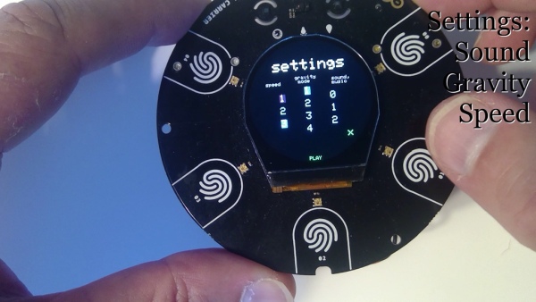
My simple menu follows the idea of a honeycomb. We have three columns. Speed, gravity and sound. Each column defines one setting. So we have three speeds for the ball, four gravity modes (which are not implemented in the present release of the game), and three sound modes (off, only sound effects, both sound effects and music).
You tilt the device to move the cursor (which is tinted red/ocra) and press the X button to select.
Step 10: The Code, Uploading the Game to Your Device
Create a new project in Arduino IDE and save it immediately to give it a name, f.i. BreakIn.
Install the library for the MKR IoT Carrier, if you haven’t done it yet.
Pick the right board for the project. You probably have a MKR1000 or MKR 1010.
Paste the contents of BreakIn01.cpp to the editor. That will become your ino file, the main code file of your project.
Move or copy the bee.h, honeycombs.h and logo.h files to your project file.
Now you should be ready to compile and upload the game to your device.
Source: Arduino MKR IoT Carrier As a Game Console
- How is the paddle controlled in the game?
The paddle is controlled by tilting the device, which uses the 3-axis accelerometer to determine the angle. - What is the resolution of the circular colour display?
The display has a width of 256 pixels and is logically treated as a 256 by 256 pixel squared screen. - How does the ball detect collisions with the honeycomb cells?
The code checks if the corner pixels of the ball are placed on a pixel not equal to black in a pre-defined bitmap. - What tools are recommended for creating sprites?
The author recommends using GIMP for design and online tools like ImageConverter or LVGL tools for converting images to C code. - How is transparency handled for non-rectangular sprites?
Transparency is managed using a masked sprite system where a separate 1-bit mask image defines which pixels are opaque or transparent. - How are sounds generated in this project?
Sounds are produced using a simple piezo buzzer that generates square wave tones at specific frequencies. - Why is the honeycomb pattern used instead of rectangular tiles?
A rectangular set of tiles would look dull on the circular screen, so a hexagonal honeycomb pattern was chosen for better aesthetics. - Can the MKR IoT Carrier connect to the internet directly?
No, the Carrier does not contain hardware for net communication; a separate microcontroller board like the MKR WiFi 1010 is required. - How is the bat position calculated mathematically?
The coordinates are calculated using trigonometric functions (cosine and sine) based on the tilt angle and a fixed radius from the center.