Summary of Arduino Mega Tutorial – Pinout & Schematics
This article details the Arduino Mega 2560 board, highlighting its features such as extensive I/O capability with 54 digital and 16 analog pins, inbuilt RTC, advanced timers, analog comparator, and multiple communication protocols (SPI, I2C, USART). It emphasizes the board's suitability for complex projects due to its large memory, debugging support, power-saving modes, and compatibility with various logic levels. The article explains pin functions, interrupts, and power supply options, and provides simple example programs for basic LED control, PWM dimming, and analog input reading via serial communication.
Parts used in the Arduino Mega 2560 Project:
- Arduino Mega 2560 Board
- 16 MHz Crystal Oscillator
- Bypass Capacitors (for crystal oscillator)
- Reset Circuit Components (push button, capacitor, resistor)
- External Power Supply (7-12V DC jack)
- Pull-up Resistors (for I2C lines)
- LED
- Push Button
- Relay (as output device example)
- Buzzer (as output device example)
- LCD Display (for I2C/SPI communication example)
- Digital Thermistor (as input device example)
- Ultrasonic Sensor (input device example)
- Joystick (input device example)
First of all, Why Arduino Mega?
When cheaper boards are available, why go with Arduino Mega? The main reason behind this is the additional features that are inbuilt with this board. First feature is the large I/O system design with inbuilt 16 analog transducers and 54 digital transducers that supports with USART and other communication modes. Secondly, it has inbuilt RTC and other features like analog comparator, advanced timer, interrupt for controller wakeup mechanism to save more power and fast speed with 16 Mhz crystal clock to get 16 MIBS. It has more than 5 pins for Vcc and Gnd to connect other devices to Arduino Mega.
Other features include JTAG support for programming, debugging and troubleshooting. With large FLASH memory and SRAM, this board can handle large system program with ease. It is also compatible with different type of boards like high-level signal (5V) or low-level signal (3.3V) with I/O ref pin.
Brownout and watchdog help to make system more reliable and robust. It supports ICSP as well as USB microcontroller programming with PC.
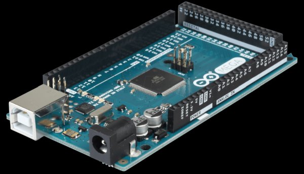
The Arduino Mega 2560 is a replacement of the old Arduino Mega, and so in general reference, it will be called without the ‘2560’ extension. It is usually used for very complex projects.
Arduino Mega 2560 is also packed with additional features like Analog Comparator, External Interrupt & Software Interrupt, Power Saving Mode, Inbuilt Temperature Sensor, RTC and more.
Arduino Mega Pinout
Arduino Mega Pin Diagram
Controller Pins:
RESET: (Reset input) A low level on this pin for longer than the 4 clock cycle will generate a reset. Arduino Mega has inbuilt reset circuit with push button to reset system and this pin can be used by other devices to reset controller.
XTAL1,XTAL2: Crystal (16Mhz) is connected to supply clock for controller with 2 bypass capacitor to ground.
AREF: This pin is used, when we use Adc for analog to digital conversion with external reference voltage for conversion and don’t want to use internal 1.1V or 5v reference.
Digital pins (70):
Digital pins (0-53) + Analog (0-15) = Total Digital I/O pins.
Digital Pins: From 0-53(digital) and 0-15(analog) can be use as input or output for digital transducer and output devices by pinMode() for pin direction, digtalWrite() to write pin and digitalRead() to read pin status.
Application:
Output devices : Relay, LED, buzzer, LCD and others.
Input devices: digital thermistor, push button, ultrasonic sensor, joystick and others

Example:
- Output low signal on Arduino mega board
pinMode(0,OUTPUT);
digitalWrite(0,LOW);
- Input read signal on Arduino mega board
pinMode(0,INPUT);
digitalRead(0);
Analog Pins (16):
Analog pins: From 0-15(analog) can be used as analog input pin for adc, if not used than it work as normal digital pin. It can be used by pinMode() for pin direction, analogRead() to read pin status and get digital value for analog signal, care must be taken for internal or external reference voltage selection and Aref pin.
Application :
Input devices: Ntc thermistor, sensors (like ldr, irled and humidity) and others
Example :
- INPUT analog signal on Arduino mega board
pinMode(0,INPUT);
analogRead(0);
Alternative Pins Function:
SPI Pins:
Pin 22 - SS, Pin 23 - SCK, Pin 24 - MOSI, Pin 25 – MISO
These pins are used for serial communication with SPI protocol for communication between 2 or more devices. SPI enable bit must be set to start communication with other devices.
Application:
Programming AVR controller, communication with others peripheral like LCD and SD card with four-line communication at high speed.
I2C Pins:
Digital pin 20 for SDA and 21 for SCK (Speed 400khz) to enable two wire communication with others devices. Function used are wire.begin() to start I2C conversion, with wire.Read() to read i2c data and wire.Write() to write i2c data.
Application:
Output devices : LCD and communication between multiple devices with two wire.
Input devices : rtc and others.
Example:
I2c master read data from slave
Wire.begin();
Wire.requestFrom(2, 1); //1byte data
Wire.Read();
PWM Pins:
Digital pin 2-13 can be used as PWM output with analogWrite() to write pwm value from 0-255.It’s alternative of DAC for low cost system to get analog signal at output by using filter.
Application:
Output devices: speed control of motor, light dimmer, pid for efficient control system.
Example:
- OUTPUT analog signal on Arduino mega board
pinMode(0,OUTPUT);
analogWrite(0,255);
USART Pins :
Pin 0 – RXD0, pin 1 – TXD0

Pin 19 – RXD1, pin 18 – TXD1

Pin 17 – RXD2, pin 16 – TXD2

Pin 15 – RXD3, pin 14 – TXD3
This pin is used for serial usart communication with pc or other system for data sharing and logging. It is used with serialBegin() to set baud rate setting and start communication with serial.Println() to print array of char on other device output.
Application:
Two controller communication, pc and controller communication, debugging with usart by serial monitor.
Example:
Serial.begin(9600);
Serial.Println(“hello”);
Pinchange Interrupt Pins:
Digital Pin 0,22,23,24,25,10,11,12,13,15,14

Analog Pin 6,7,8,9,10,11,12,13,14,15
This pin is used for pin change interrupt. Enable bit of pinchange interrupt must be set with global interrupt enable.
Application :
Rotary encoder, push button based interrupt and others.
Example :
pinMode(0, OUTPUT);
pinMode(1, INPUT_PULLUP);
attachInterrupt(digitalPinToInterrupt(1), LOW, CHANGE);
Hardware Interrupt Pins :
Digital pin 18 – 21,2,3 hardware interrupt is used for interrupt services. Hardware interrupt must be enabled with global interrupt enable to get interrupt from other devices.
Application:
Push button for ISR program, wake up controller with external devices, sensors like ultrasonic and others.
Example:
pinMode(0, OUTPUT);
pinMode(1, INPUT_PULLUP);
attachInterrupt(digitalPinToInterrupt(1), LOW, LOW);
Arduino Mega Schematic Components:
DC Jack Power Supply :
External Supply for Arduino Mega from range 7-12 volt is given with this port. Arduino Mega R3 has a voltage regulator for 5v and 3.3v supply for Arduino controller and sensor supply.
AVR 2560 :
This is the main controller used to program and run task for the system. This is the brain of the system to control all other devices on board.
ATmega8 :
This controller is used for communication between the main controller and other devices. This controller is programmed for USB communication and serial programming features.
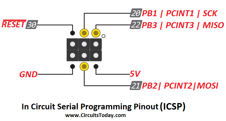
ICSP 1 (ATmega8) and 2 (AVR 2560):
It has features of programming using serial bus with AVR programmer using SPI communication. AVR 2560 is programmed to run the system and ATmega 8 is programmed for serial communication and programming.
Reset :
It has reset circuit with capacitor, button and resistor to reset the controller. A push button is used to get 4 cycle low signal on reset pin to get the controller in reset mode.
Crystal :
It has a crystal circuit with two capacitors and one 16 Mhz crystal for xtal pins 1 and 2 interfacing with avr 2560.
I2C :
It has features of I2C (two wire communication) with an external pull-up resistor.
USART :
It has TXD and RXD pin for serial communication with LED indicator.
Some Simple Programs to try on Arduino Mega 2560
Program 1: Blinking LED (Digital pin)
/*

Turns on an LED on for two second, then off for two second on pin 13, repeatedly.

*/

// the setup function runs once when you press reset or power the board

void setup() {

// initialize digital pin 13 as an output.

pinMode(13, OUTPUT);

}

// the loop function runs again and again

void loop() {

digitalWrite(13, HIGH);   // turn the LED on (HIGH is the voltage level)

delay(2000);                       // wait for two second

digitalWrite(13, LOW);    // turn the LED off

delay(2000);                       // wait for two second

}
Program 2: Led Light Dimmer (PWM):
int brightness = 0;    //pwm value

void setup()

{

pinMode(3, OUTPUT);

}

void loop()

{

analogWrite(3, brightness);  // pwm write on pin 3

++brightness;  // brightness is incremented by 1

if (brightness <= 0 || brightness >= 255) {

brightness=0;  // brightness limited to 0-255

}

delay(10);

}
Program 3: Analog Read Voltage (Analog pin with USART) :
void setup()

{

Serial.begin(9600);  // usart communication start function with baudrate set to 9600

}

void loop()

{

int sensorValue = analogRead(A0);  // analog pin 0 data is read and converted into digital value stored in sensorValue.

Serial.println(sensorValue); // usart to output sensor value on serial monitor

}
You may also try your own logic and implement programs for Arduino mega with basic C and Arduino function.
Source : Arduino Mega Tutorial – Pinout & Schematics