Summary of Arduino Light Meter Circuit
This article explains building an Arduino-based light meter using a generic analog volt panel meter and a photoresistor. The circuit functions as a voltage divider where the photoresistor's resistance changes with light levels, causing the meter needle to deflect proportionally to brightness. This setup allows users to visually gauge light intensity without precise lumen or lux calibration.
Parts used in the Arduino Light Meter:
- Analog Panel Meter
- 100KΩ Resistor
- GL5537 Photoresistor
In this project, we will go over how to connect an analog volt panel meter to an Arduino so that it can measure and give us a readout of light striking the circuit.
 In this way, the circuit will function as a light meter.
When there is a lot of light shining on the circuit, the meter will deflect greatly. When there is a low level of light hitting the circuit, the meter needle will barely deflect. In this way, we have a device that deflects based on the light level hitting it.
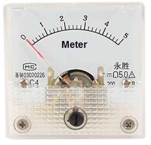
The type of analog panel meter we will use is really generic. Light is usually measured in unit lumens, lux, or candela. However, it will be very difficult to find an panel meter that is calibrated in terms of lumens, lux, or candela. So a generic panel meter can be used that is calibrated in volts. If the circuit is set up properly, the idea is that you can still see how much the needle swings in proportion to changes in light, even if an exact value can’t be read. If the needle barely moves at all, it is exposed to either darkness or very small amount of light. If the needle swings about midway, it’s exposed to a decent level of light. If the needle swings all the way left, bright light is being shone on it.
This way, we can demonstrate how to build a light meter.
For this circuit to work, the component that will be used to detect and measure the amount of light is a photoresistor. A photoresistor is a type of special resistor whose resistance changes in proportion to the amount of light exposed to it. When exposed to darkness, it offers a great amount of resistance. Depending on the type, it can be megohms of resistance. When exposed to bright light, its resistance drops drastically. Again, depending on the type it may fall below 30KΩ. We will build a voltage divider circuit so that we place a photoresistor in series with a fixed resistor. Since the photoresistor changes its resistance in response to light and changed resistance incurs changed voltage, we can measure the amount of voltage the photoresistor has and know whether it is exposed to a bright light (low resistance) or darkness (high resistance). If the photoresistor is exposed to darkness, it will have a very high resistance. Thus, in a voltage divider circuit, most of the voltage will fall across the photoresistor and not the fixed resistor. Thus, we will write our code so that under this condition, the needle does not deflect much. If the photoresistor is exposed to bright light, it will have very low resistance, much less than that of the fixed resistor. Thus, most of the voltage will fall across the fixed resistor and very little across the photoresistor. Under this condition, we write our code so that the needle deflects far right.
Components Needed for the Arduino Light Meter Circuit
- Analog Panel Meter
- 100KΩ Resistor
- GL5537 Photoresistor
The analog panel volt meter we will use can be found at Sparkfun here: Analog Panel Meter- 0-5VDC. This can measure from 0V to 5V of DC voltage with 2.5% accuracy. It’s fairly accurate. This volt meter can play the role as our light meter for this circuit.
The GL5537 photoresistor comes in GL5537-1 and GL 5537-2. Both are acceptable to use for this circuit. The GL5537-1 has a dark resistance of 2MΩ and a light resistance of 20-30KΩ. The GL5537-2 has a dark resistance of 3MΩ and a light resistance of 3-50KΩ. Any photoresistor can be used that can has similar specs.
We want our photoresistor to have a dark resistance much higher than the fixed resistance and a light resistance much lower than the fixed resistance, to provide a contrast in the voltage divider circuit. Since our fixed resistor will be 100KΩ, the GL5537 will work great with this fixed resistor for this purpose.
Arduino Light Meter Circuit Schematic
The Arduino light meter circuit we will build is shown below.
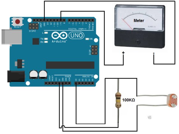
The circuit connections are pretty straightforward and basic.
When connecting the analog volt panel meter to the Arduino, we connect one terminal to D9 of the Arduino and the other terminal to ground (GND).
For more detail: Arduino Light Meter Circuit
- How does the circuit measure light?
The circuit uses a photoresistor in a voltage divider configuration where resistance changes with light exposure to alter the voltage read by the meter. - Can I use a standard voltmeter instead of a panel meter?
A generic analog panel meter calibrated in volts is used because meters calibrated in lumens or lux are difficult to find. - What happens to the needle when there is bright light?
When exposed to bright light, the photoresistor resistance drops, causing the needle to deflect far right. - What happens to the needle in darkness?
In darkness, the photoresistor has high resistance, so the needle barely deflects or stays near the left side. - Which specific photoresistor models are recommended?
The GL5537-1 and GL5537-2 models are acceptable as they have suitable dark and light resistance specifications. - Why is a 100KΩ resistor used in the circuit?
A 100KΩ fixed resistor is chosen because it provides the necessary contrast against the photoresistor's varying resistance for the voltage divider. - How do I connect the analog panel meter to the Arduino?
Connect one terminal of the meter to digital pin D9 on the Arduino and the other terminal to ground. - Does the project provide exact lux readings?
No, the device shows proportional deflection based on voltage rather than providing exact values in lux or candela.