This instructable shows you how to use NES controller in Atari 2600 or ZX Spectrum (with Kempston Interface) with the aid of an Arduino.
Step 1: Background talk
I have recently acquired a couple of Atari 2600s and a bunch of joysticks. Both consoles were working but all of the 5 joysticks were damaged beyond repair. Indeed, it is very easy to find It is easy to find an old Atari 2600 console working but it’s hard to find an original joystick in useful condition.
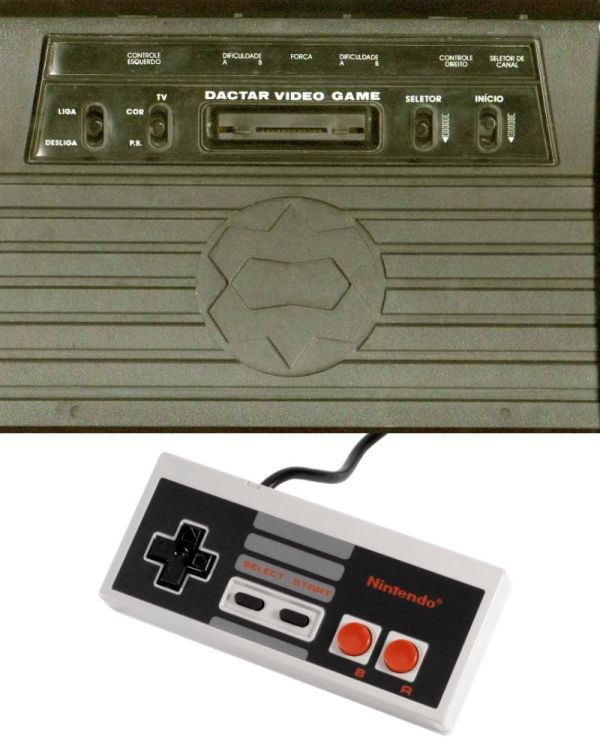
On the other hand, I had a spare NES ‘generic’ controller bought in a flea market that was working perfectly.
I thought about using a microcontroller to convert the serialized signals in NES joystick to parallel signals required by Atari 2600, but then I wondered that if instead of a custom microcontroller board I could use an Arduino. So other people without many skills in electronics could assemble their own adaptors with easy.
Step 2: The ‘big’ Circuit
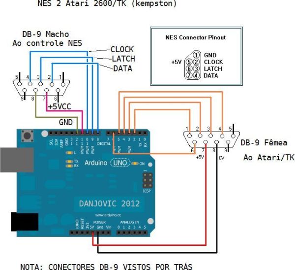
The circuit uses only the Arduino and a couple of connectors. The code is very small, so any Arduino board will do. But either way here follows the list.
Bill of Materials:
– 1 Arduino (any version will do)
– 2 DB-9 Male connectors. One for the NES ‘generic’ Controller and another to the test dongle
– 1 DB-9 Female connector, to plug into the Atari.
– 5 Leds for the test dongle
– 5 resistors 330 Ohms 1/4 Watt for the test dongle
– A buch of wires
Of course is it possible to reuse the old Atari Joystick cable instead of the DB9 female plus wires.
It is also possible to cut the NES controller cable and connect directly to the Arduino, but you should identify the wires in the cable.
Step 3: Programming the Arduino and doing some tests
Compile and upload the code below to the Arduino. It was developed using IDE version 0.22. Before connecting the circuito to the ATARI use use a Dongle to verify the correct behavior of the circuit. The leds in the dongle shall be activated according with the buttons in the NES controller. Both action buttons are mapped to the same (and sole) Atari button. For the test with the dongle it is necessary to power the Arduino board.
//
// Play on ATARI 2600 with NES Controller By Danjovic, 2012
// Compiled on Arduino 0.22
//
/*
ATARI 2600 Joystick
Activates sequentially the following directions from an Atari 2600 Joystick
UP, DOWN, LEFT, RIGHT, TRIGGER
CONNECTIONS ON ATARI JOYSTICK
Function DB-9 Arduino AVR
UP 1 Pin 2 (PD2)
DOWN 2 Pin 3 (PD3)
LEFT 3 Pin 4 (PD4)
RIGHT 4 Pin 5 (PD5)
+5VCC 5 +5V +Vcc
TRIGGER 6 Pin 6 (PD6)
GND 9 GND GND
*/
/*
NES Controller
Contains a CMOS Shift Register (CD4021). Data change on raise border of Clock
button sequence as below.
– 2 DB-9 Male connectors. One for the NES ‘generic’ Controller and another to the test dongle
– 1 DB-9 Female connector, to plug into the Atari.
– 5 Leds for the test dongle
– 5 resistors 330 Ohms 1/4 Watt for the test dongle
– A buch of wires
For more detail: Arduino lets you play Atari 2600 and ZX Spectrum using a NES controller