What
This button pad is made using a PCB and other components manufactured by Sparkfun. It is driven by an Arduino Mega. Each button is nice and squishy and satisfying to press, and it has an RGB LED inside!
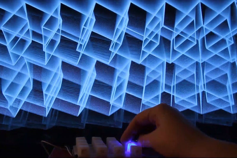
I’ve been using it to control animations I’ve coded in Processing. The button pad sends a message whenever a button is pressed, saying which button it was. Processing receives these messages and changes variables in the sketch depending on what was pressed.
Why
LEDs are cool.
Buttons are fun to push.
Animated geometric patterns are nice.
I wanted to combine all three.
I took this project to a party, projected the visuals on the wall and let people play with the buttons. It could also be used by a VJ in a more performative way, much like a midi controller but more DIY.
How
There are four main parts to this project.
The attached Youtube video gives a good look at how the button pad goes together. This Instructable covers that as well as the Arduino and Processing code – (additional videos for those are in the works)
- Putting the button pad together – Starts in Step 1
This involves preparing the components and soldering them to the PCB - The Arduino code – Starts in Step 10
For this, we need an understanding of matrix scanning, which I will talk through. - The Processing code – Starts in Step 24
There are endless possibilities here, I’ll talk through one example I’ve made so far. - Getting the Arduino to send messages to Processing – Step 16 for sending, Step 30-31 for receiving
This is nice and simple, it sends the message over a serial connection.
Level
I try and write my tutorials in such a way that someone with absolutely no knowledge at all can at least follow along. You might find it helpful to first watch some introductory tutorials about Processing. I’d start with Daniel Shiffman’s YouTube channel.
Code
All of the code (Arduino and Processing) is on my github here.
Credits
I learnt a bunch from this tutorial https://learn.sparkfun.com/tutorials/button-pad-ho… and much of the Arduino code is from there, although I have edited it to work slightly differently from any of the examples there.
Step 1: The Components!
- 16 x 5mm RGB LEDs (not addressable ones, just regular common cathode ones)
- 16 x 1N4148 diodes
- Silicone button pad
- Button pad PCB
- Arduino Mega
- Jumper cables
- (There’s also a bunch of stuff you can get from Sparkfun to house the whole thing a bit more neatly, but I have not done this)
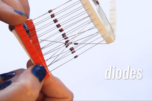
Step 2: Prepare the Diodes
Bend each diode and then push it through the PCB.
The legs stick out on the button side, which we don’t want. So take the diode out again and cut the legs short. (You might have some snips that will let you cut the legs flush with the board while it’s still in there which will make your life easier, but I only had normal scissors so I had to pull them out to cut them short enough.)
It is super important to bend the legs and push them through the PCB before you cut them short. If you cut them short first then you won’t be able to bend them into shape.
Make 16 of these little ant-like thingies.
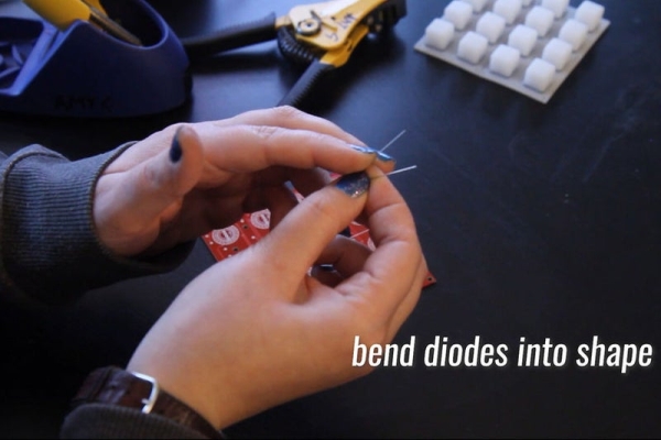
Step 3: Solder the Diodes Onto the Board
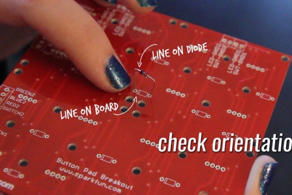
Place each of the diodes back into the board. Its important to check the orientation of the diode. It has a black line on one side which lines up with the line on the PCB. (See image)
Getting the diodes into place is kind of fiddly which is why I said if you have snips that will let you cut the legs flush without removing them, it will make your life easier. I didn’t have that so I used tweezers to place them back in, which helped a bit.
Solder each of the diodes into place.
Step 4: Prepare the LEDs
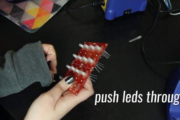
Push the LEDs through the board and then cut the legs off. Just like with the diodes; its important to push the legs through the board first, to get them spread to the correct angles, before cutting the legs.
There’s a bit of trial and error with cutting the legs to the right length. If you make them too long they will stick out, but too short and it’s difficult to get the LED back in.
Prepare 16 of these little amputated fellas.
Step 5: Solder the LEDs Onto the Board.
Push all the LEDs back into the board.
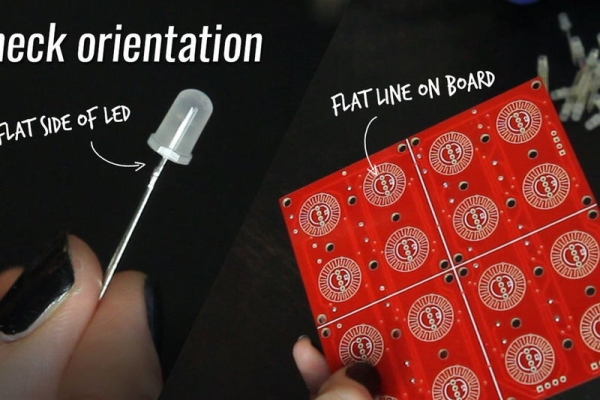
The orientation is important again here. One side of the LEDs has a flat edge and this should line up with the flat edge of the circle on the PCB diagram. (See image)
See if the LEDs are pushed in far enough by putting the silicone pad over the board and checking that they don’t interfere with the buttons being pushed.
Solder the LEDs onto the board.
Note: It’s since been pointed out to me that since it doesn’t matter so much if a bit of the legs sticks out on the back, you could just push the LEDs through, solder them at the back, and then cut the legs off.
Source: Arduino LED Button Pad That Drives Processing Animations