Summary of Arduino : Lead Acid Battery Capacity Tester (Updated)
This project is a programmable active load designed to discharge 12V lead-acid batteries at a constant current to measure actual capacity. It supports batteries up to 200Ah, measuring voltages between 10.1V and 14.7V with 5mV resolution and currents from 0.1A to 13.9A. The system uses an Atmega328 microcontroller, OLED display, EEPROM for data logging, and user-controlled buttons to set discharge rates or C-Rates (5, 10, or 20 hours). Testing stops automatically at cutoff voltage or elapsed time.
Parts used in the Lead Acid Battery Capacity Tester:
- Atmega328 Microcontroller
- MOSFET (Q1)
- High Wattage Resistors Network (R1)
- OLED Display
- EEPROM
- S1/S2 Buttons
- AVR Internal Timer1
Story
Yosh ! At last, finished working on this project. I have been working on this project for a while, then got bored and left the remaining work ( mostly firmware ) for a couple of months, ah ! the longest project I ever did !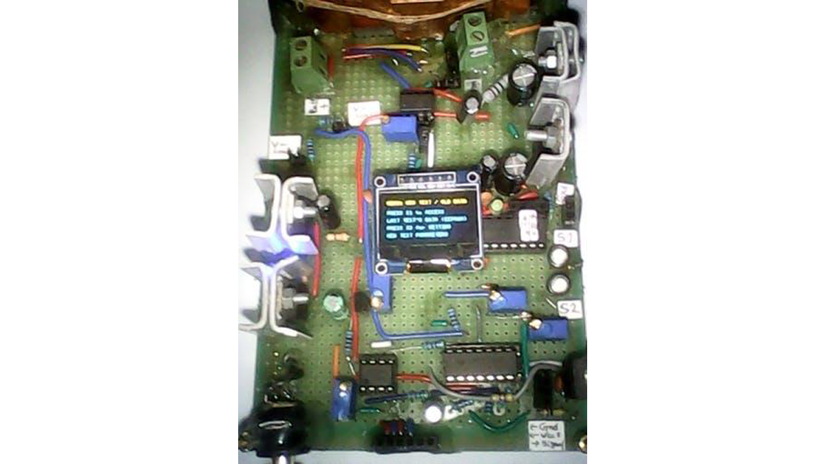
What’s all this about ?
This project is about discharging lead acid battery at a constant current to measure its actual capacity.
Due to hardware and design constrain there are few limitations :
Only 12 Volts Lead Acid Batteries up to 200Ah can be Discharge ! Because of measurement offset (to achieve better Voltage Measurement Resolution) only Voltages from 10.1 V to 14.7 V can be measured, which means any voltage below 10.1 volt will read 10.1 volt. Besides, a 12 Volt Lead Acid Battery that reads 10 volt is practically Dead !
Current Measurement Resolution is 25 mA to cover a wider measurement range (0-13.9 A) which can be a problem for measuring very small Discharge Rate ( below 300 mA )
Voltage Measurement Resolution is 5 mV. Measured voltages are stored in EEPROM periodically (every 5th minute) and exported through USB-Serial after the test is completed.
Discharge Current can be (Set) Programmed by User through S1/S2 buttons and which can be any value multiple of 0.1 A (100mA) from 0.1 A to 10.0 A.
C-Rate (which is equal to Discharge Time/Expected Test Duration) can be configured by User for 5 hrs or 10 hrs or 20 hrs. For example if a 35 Ah Battery is discharged at a C-Rate of C/10 then the Discharge Current will be 3.5 A (3500 mA) and the expected Discharge Duration should be 10 hrs.
Test can be Aborted by user (with proper Ramp Down of Current to 0 A) by pressing S1/S2 buttons according to the instructions shown on OLED screen Menu !
During the Test Run the OLED Display will show Test Time, Discharge Current, Battery Terminal Voltage on the screen.
Test will stop automatically whenever Battery Cut Off (here 10.5 V) is reached or Time (=C hrs) is elapsed.
Time keeping is done using the AVR internal Timer1 with Interrupt. S1/S2 Buttons are connected to INT0/INT1 of Atmega328 microcontroller for controlling User Interface.
How Does it Work ?
The LOAD through which the discharge current runs is a Programmable Active Load. It is driven such a way that a constant current flows through it regardless of the drop of battery voltage over time due to discharge !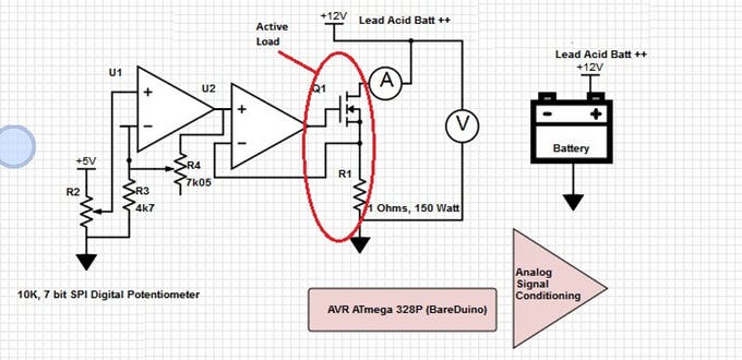
Active Load consists of a MOSFET(Q1) and High Wattage Resistors Network (shown as single Resistor R1) , the MOSFET’s Drain to Source Channel acts as a Variable Resistor and the High Wattage Resistor Network has a Fixed Value Resistance (until it heats up too much).
For more detail: Arduino : Lead Acid Battery Capacity Tester (Updated)
- What is the primary purpose of this project?
The project discharges lead acid batteries at a constant current to measure their actual capacity. - Can this device measure voltages below 10.1 volts?
No, due to measurement offset, any voltage below 10.1 V will read as 10.1 V. - How is the discharge current controlled by the user?
Users program the discharge current using S1/S2 buttons in multiples of 0.1 A from 0.1 A to 10.0 A. - What C-Rate options are available for configuration?
Users can configure the test duration for 5 hours, 10 hours, or 20 hours. - How often are measured voltages stored in memory?
Measured voltages are stored in EEPROM every 5th minute during the test. - Does the device stop automatically under certain conditions?
Yes, it stops when the battery reaches the cut-off voltage of 10.5 V or when the configured time elapses. - How does the active load maintain constant current?
The MOSFET acts as a variable resistor while the high wattage resistor network provides fixed resistance to ensure constant current flow. - What information is displayed on the OLED screen during testing?
The screen shows Test Time, Discharge Current, and Battery Terminal Voltage.