Summary of Arduino LCD
This tutorial guides users in connecting a 16x2 HD44780-compatible LCD to an Arduino Uno, preparing the display by soldering headers if necessary, and running built-in IDE examples. It details wiring the circuit in 4-bit mode, utilizing a potentiometer for contrast adjustment and a resistor for backlight current limiting, while emphasizing correct pin alignment to prevent hardware damage.
Parts used in the Arduino LCD Project:
- Arduino Uno board
- USB cable
- Wire links
- Breadboard
- 47 ohm resistor (yellow - violet - black)
- 10k potentiometer
- 16x2 character LCD (HD44780 compatible)
- 16 way single in-line pin header
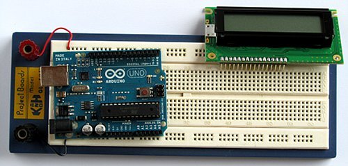
In this tutorial you will connect a LCD (Liquid Crystal Display) to the Arduino Uno and then run the Arduino LCD example programs that are built into the Arduino IDE.
Prerequisites
It is recommended for beginners to complete all the Arduino tutorials up to and including Tutorial 10: Ten Arduino Projects for Absolute Beginners.
Read about Liquid Crystal Displays (LCD). You will also need to prepare your LCD by soldering wires or a pin header to the display unless your LCD already has connections that allow you to connect it to a breadboard. Read the article on soldering irons and on soldering. The article on soldering has a video that shows how to solder a pin header to a LCD display.
Components
Besides an Arduino Uno board, USB cable, wire links and a breadboard, you will need:
| Qty | Part | Designator | Notes | Type |
|---|---|---|---|---|
| 1 | 47 ohm resistor (yellow – violet – black) | R1 | 1/4W, 5% or better
Only needed if using LCD backlight |
Resistors |
| 1 | 10k potentiometer | RV1 | Trimpot or panel mount. Used for LCD contranst | Potentiometer |
| 1 | MSC-C162DYLY-4N (Truly) or PC1602LRS-FWA-B (Powertip) or similar | 2 line by 16 character LCD, HD44780 compatible
The display can be with or without backlight. The two parts mentioned here both have backlights. |
Semiconductor | |
| 1 | 16 way single in-line pin header | Single in-line pin header, 16 pins (2.54mm pin spacing) to be soldered into LCD for connection to breadboard | Header |
Circuit Diagram
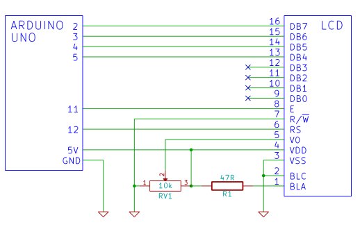
Before wiring up your LCD to the Arduino, make sure that your LCD has the same pin numbering as the one in the circuit diagram below. If it does not, you will need to make sure that you make the correct connections between the LCD and Arduino. Also refer to the Arduino Liquid Crystal page for connections to a different LCD that has pins at the top of the LCD instead of at the bottom. The pin numbering on the physical LCD used in this tutorial can be found on the LCD page. When building the circuit, you will need to refer to the diagram or photo showing the physical pin numbering / pin names of the LCD to make sure that you are connecting the LCD correctly.
The circuit diagram shows that the following connections are made:
| Arduino | → |
LCD |
| Pin 2 | → | DB7 |
| Pin 3 | → | DB6 |
| Pin 4 | → | DB5 |
| Pin 5 | → | DB4 |
| Pin 11 | → | E (Enable) |
| Pin 12 | → | RS |
The following are all connected to the Arduino GND:
- The LCD R/W pin
- One of the outer pins of the potentiometer
- The LCD VSS pin
- The LCD backlight cathode pin (BLC)
The centre pin (or wiper) of the potentiometer is connected to the LCD V0 pin.
The following are connected to the Arduino 5V pin:
- The LCD VDD pin
- One of the potentiometer outer pins
- The LCD backlight anode pin (BLA) is connected to 5V through a 47Ω resistor
The first four data pins of the LCD (DB0 to DB3) are left disconnected as the LCD will be run in 4-bit mode where these pins are not needed.
The 47 ohm resistor provides current limiting for the LCD backlight and will not be needed if your LCD does not have a backlight.
The 10k potentiometer adjusts the LCD contrast. After powering up the circuit, you will need to adjust the contrast pot. until you can see the dots of the display or characters being displayed if a program (sketch) has been loaded to the Arduino and has written to the LCD.
Building the Circuit
After preparing your LCD display by soldering a pin header to it, get ready to plug it into the breadboard. Also be sure to check the datasheet for your LCD to see what the pin names are so that you can connect it correctly. Be very careful not to connect the LCD power pins the wrong way around as this will most likely destroy the LCD.
For more detail: Arduino LCD
- What is recommended before starting this tutorial?
Beginners should complete all Arduino tutorials up to Tutorial 10. - How do I prepare an LCD without existing connections?
You must solder wires or a pin header to the display. - Which pins on the Arduino connect to the LCD data lines?
Pins 2, 3, 4, and 5 connect to DB7, DB6, DB5, and DB4 respectively. - Why are the first four data pins of the LCD left disconnected?
The LCD runs in 4-bit mode where DB0 to DB3 are not needed. - What is the function of the 10k potentiometer?
It adjusts the LCD contrast. - When is the 47 ohm resistor required?
It is only needed if using the LCD backlight to limit current. - Which Arduino pin connects to the LCD Enable pin?
Arduino Pin 11 connects to the LCD E (Enable) pin. - Where does the LCD R/W pin connect?
It connects directly to the Arduino GND.