Summary of Arduino LCD Voltmeter with 4 Channels
This article describes a 4-channel Arduino Uno voltmeter project that measures independent DC voltages ranging from 0 to 50V. The system utilizes analog channels A2 through A5 with voltage dividers to scale inputs for the microcontroller. Results are displayed on a 16x2 LCD with one decimal precision. The setup includes an optional backlight controlled by a current-limiting resistor, and users must ensure correct LCD pinout alignment to prevent damage.
Parts used in the 4-Channel Arduino Voltmeter:
- Arduino Uno
- 16 character by 2 line LCD
- Voltage divider resistors (R1 and others)
- Contrast potentiometer
- Current limiting resistor for backlight
- Breadboard
- Pin headers
Analog channels A2 to A5 on an Arduino Uno are used to measure four different voltages. The measured voltages are displayed on a 16 character by 2 line LCD.
The four channel Arduino multimeter can measure four independent DC voltages that can each be in the range of 0 to 50V.
Voltages are displayed with one decimal place, e.g. 5.3V, 12.8V, etc.
This video shows the Arduino voltmeter being used to measure the voltage of four batteries. Each battery has a different voltage.
Can’t see the video? View on YouTube →
How the Voltmeter Works
Each channel of the Arduino voltmeter has a pair of resistors that form a voltage divider. The voltage divider scales down the input voltage to a range that the Arduino can measure. Code running on the Arduino calculates the actual voltage and displays the result on the LCD.
How the voltage divider works, precautions and voltage range are explained in the article Measuring DC Voltage using Arduino. The Arduino voltmeter uses the same resistor values as the article.
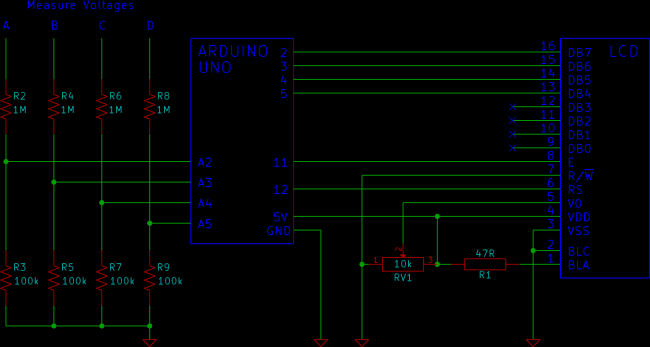
Arduino Voltmeter Circuit Diagram
The LCD used in the circuit has the pin numbering shown in the LCD component information from the beginner’s tutorial on this website.
It is important to check that the LCD that you are using has the same pin numbering as the circuit diagram. Making incorrect LCD connections can damage the LCD.
If you are using a LCD with different pin numbering, use the pinout information from your LCD’s datasheet to make the connections to the Arduino.
The Arduino LCD tutorial explains how to connect a LCD to an Arduino Uno. The soldering article has a video that shows how to connect a pin header to the LCD so that it can be plugged into a breadboard.
Voltages are measured between points A, B, C or D and GND or 0V. Remember to adjust the contrast pot. so that the voltages on the LCD are made visible.
Resistor R1 provides current limiting for an optional backlight and keeps the backlight permanently on.
Arduino Voltmeter Sketch Code
The sketch is based on the code from the Measuring DC Voltage using Arduino article.
The sum and voltage variables have been changed into arrays so that they can store values from four analog channels. The voltage calculations work the same way as the original sketch, but now do the calculations for four channels.
For more detail: Arduino LCD Voltmeter with 4 Channels
- What is the maximum voltage range this multimeter can measure?
Each of the four independent channels can measure DC voltages in the range of 0 to 50V. - How does the circuit handle high input voltages?
Each channel uses a pair of resistors forming a voltage divider to scale down the input voltage to a measurable range for the Arduino. - Which analog pins are used for measurement?
Analog channels A2 to A5 on the Arduino Uno are utilized to measure the four different voltages. - How is the voltage data presented on the display?
Voltages are displayed on the LCD with one decimal place, such as 5.3V or 12.8V. - Can the backlight be turned off?
The provided design keeps the backlight permanently on using resistor R1 for current limiting. - What should I do if my LCD has different pin numbering?
You must use the pinout information from your specific LCD datasheet to make the correct connections to the Arduino. - Where should the voltage probes be connected?
Voltages are measured between points A, B, C, or D and GND or 0V. - Why might the voltages not be visible on the screen?
You need to adjust the contrast pot so that the voltages on the LCD become visible.