Summary of Arduino LCD Metronome
This article outlines the assembly of an Arduino-based LCD metronome. It details wiring an HD44780 LCD to an Arduino, integrating a TDA7052 amplifier circuit with volume control, and connecting a rotary encoder for BPM adjustment. The project combines these components to create a functional metronome that displays elapsed time and allows user interaction via a button on the encoder.
Parts used in the Arduino LCD Metronome:
- Arduino (any normal sized)
- HD44780 LCD Display
- 3x 100K Ohm Resistors
- A rotary encoder with a button
- 1M Ohm Resistor
- TDA7052 Amp
- Speaker
- 44K Ohm Potentiometer
- 100k Ohm Potentiometer
- 100nF non-polarised capacitor
- 100uF 16v electrolytic capacitor
Connecting the LCD

Pin 1 – Vss
Pin 2 – Vdd
Pin 3 – Vo
Pin 4 – RS
Pin 5 – R/W
Pin 6 – E
Pin 7 – DB0
Pin 8 – DB1
Pin 9 – DB2
Pin 10 – DB3
Pin 11 – DB4
Pin 12 – DB5
Pin 13 – DB6
Pin 14 – DB7
Pin 15 – A
Pin 16 – KThis is how the pins should be connected:
LCD1 – GND
2 – 5v
3 – Middle pin of 44K pot
4 – Arduino 12
5 – GDN
6 – Arduino 11
11 – Arduino 5
12 – Arduino 6
13 – Arduino 7
14 – Arduino 8
15 – 5v
16 – GND
The rest of the LCD pins can be left blank. The pot needs the other pins to be connected to 5v and GND. For a more in depth look see http://arduino-for-beginners.blogspot.com/2010/11/arduino-output-lcd-modules-part-1.html
Step 3: Testing the LCD
 lcd_test.pde565 bytes
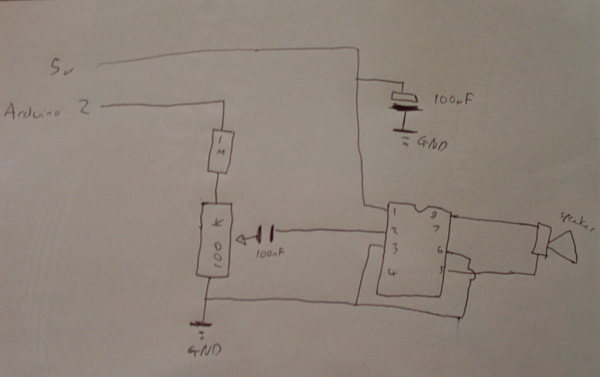
Building the amplifier
Next up is the amp circuit. Be very careful to get the IC and 100uF capacitor the right way round. The pot controls volume.
Connecting the Rotary Encoder
The final hardware step is to connect the rotary encoder. The rotary encoder is like a pot but can rotate all the way round, have a button. They work by changing the voltage between two pins.
There are 5 pins, generally 3 on top and 2 at the bottom, you will need to solder wires to the pins (they’ll short if you just plug them into a breadboard, due to the 2 at the bottom being in line with one at the top).
Pressing the button will allow you to increase the BPM in 10s, pressing again will make it go back to 1s.
Look at the drawing below for how to wire them.
– Arduino (any normal sized Arduino will be fine)
– The Arduino IDE and the knowledge to use it
– Lots of wires
– HD44780 LCD Display (I’ve used a 20×4 but a 16×2 will work fine)
– 3x 100K Ohm Resisors
– A rotary encoder — must have a button
– 1M Ohm Resistor
– TDA7052 Amp
– Speaker
– 44K Ohm Potentiometer
– 100k Ohm Potentiometer
– 100nF non-polarised capacitor
– 100uF 16v electrolytic capacitor
For more detail: Arduino LCD Metronome
- What is the first step in building this project?
The first step is to wire up the LCD using the specified pin connections. - How do you test if the LCD is working correctly?
You upload the attached code and should see Hello world text and the number of seconds since upload. - What should you do if there is a backlight but no text?
You should try turning up the potentiometer. - Which component controls the volume in the amplifier circuit?
The pot controls the volume in the amp circuit. - Can you plug the rotary encoder directly into a breadboard?
No, you must solder wires to the pins because they will short if plugged directly due to the bottom pins being in line with one at the top. - How does pressing the rotary encoder button affect the BPM?
Pressing the button increases the BPM in 10s increments, and pressing again changes it back to 1s increments. - Does the type of LCD display matter for this project?
A 20x4 display was used, but a 16x2 will work fine as well. - What happens if the IC or capacitor is installed incorrectly in the amp circuit?
The article warns to be very careful to get the IC and 100uF capacitor the right way round.